High power ultrasonic transducer

a transducer and ultrasonic technology, applied in the direction of transducer types, piezoelectric/electrostrictive devices, sound producing devices, etc., can solve the problems of material depolarization, material depolarization, and material depolarization

Inactive Publication Date: 2000-10-24
ULTRASONUS
View PDF4 Cites 43 Cited by
  • Summary
  • Abstract
  • Description
  • Claims
  • Application Information

AI Technical Summary

Problems solved by technology

The casing of a submersible transducer is sealed for the transducer to be operative under water, thereby making the removal of excess heat from the transducer difficult.
Thus, encasing the piezoelectric elements of a transducer will reduce the thermal conductivity between the piezoelectric element of elements and the medium surrounding the transducer, thereby reducing the cooling of the piezoelectric element(s).
--the material will depolarize and become useless.
This is especially pronounced in the case of high power transducers, wherein the higher power applied can generate considerable internal heat in the piezoelectric elements as well as in the encasement of the transducer, especially if the total resonance system does not have a proper acoustical and electrical tuning.
Although these phenomena are not limited to encased transducers only, the occurrence of arcs is still a disadvantage in addition to the degeneration caused by high temperature.
The conventional way to reduce the arc effect has been to immerse the stack of piezoelectric elements in an insulating medium, but this has also the effect to further reduce the thermal conductivity between the piezoelectric elements and the surrounding of the transducer.
Although a dielectric medium applied with pressure to the piezoelectric degrading arcs, the problem of low thermal conductivity remains.

Method used


Image

  • High power ultrasonic transducer
  • High power ultrasonic transducer
  • High power ultrasonic transducer

Examples


Embodiment Construction

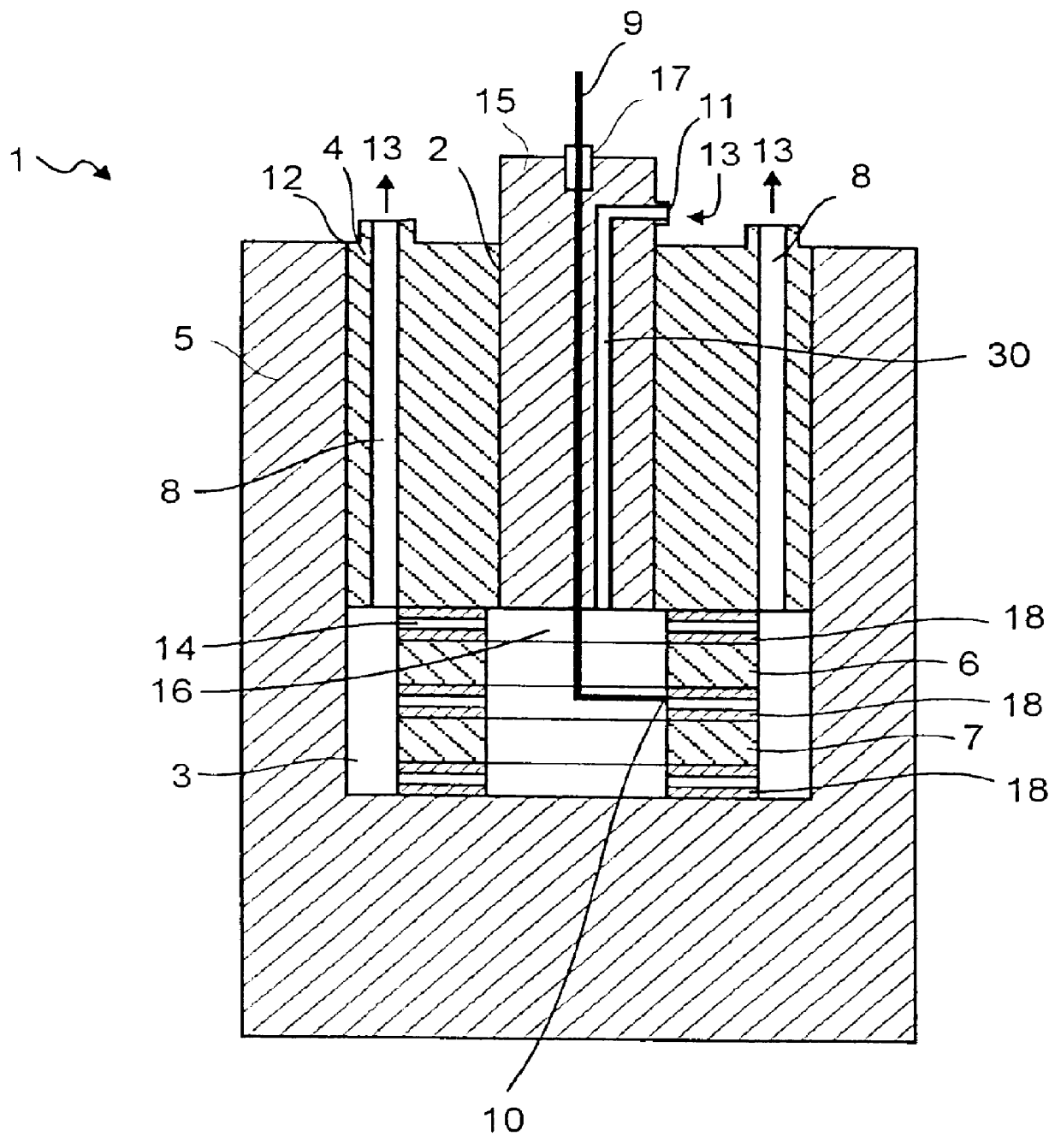
The temperature of piezoelectric elements in an ultrasonic transducer will increase during operation because of the friction within the piezoelectric materials and also because acoustic energy is trapped inside the transducer if the transducer system is not properly tuned. Therefore, it becomes obvious that the piezoelectric material can only transmit ultrasonic energy at a level that allows the material to work at a temperature so low, that it can maintain its effective properties during its useful lifetime.

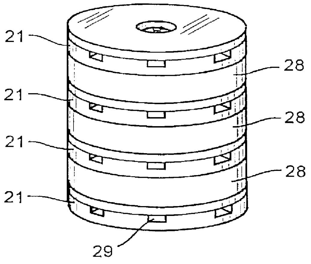
According to the present invention, a method that allows an encased ultrasonic transducer with stacked piezoelectric elements to transmit ultrasonic energy at a raised level by way of cooling the piezoelectric elements includes the steps of:

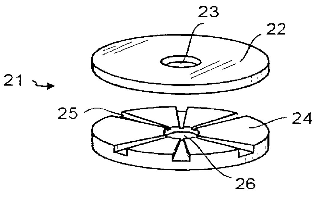
providing the transducer with at least one gas inlet and at least one gas outlet;

providing a gas conducting means for cooling the piezoelectric elements between at least one pair of adjacent elements, such that a gas from the gas inlet can fl...


PUM


Abstract

A method to improve the high output characteristics of a ultrasonic transducer 1 by urging a cooling gas 13 to flow through the transducer, thereby passing a cooling member 18 between at least one pair of adjacent piezoelectric elements 6, 7. In a preferred embodiment sulfurhexafluoride (SF6) is used as cooling gas.

Description

The present invention relates to ultrasonic transducers, and more specifically to high power ultrasonic transducers with piezoelectric elements for use under conditions of reduced thermal conductivity with respect to the surroundings.PRIOR ARTUltrasonic transducers sometimes have to be utilized under conditions of an environment having reduced thermal conductivity. For example, this is the case for submersible transducers, as well as for transducers working in surroundings of high temperatures.Regardless of design of transducer, a high ambient temperature constitutes an environment of reduced thermal conductivity. The heat generated by the piezoelectric elements of the transducer tends to build up a high intrinsic temperature within the transducer, rather than the heat being transferred to the surroundings.In a submersible ultrasonic transducer the heat is captured within the transducer. The casing of a submersible transducer is sealed for the transducer to be operative under water,...

Claims


Application Information

Patent Timeline
Patent Type & Authority Patents(United States)
IPC IPC(8): B06B1/06G10K11/00H04R1/02H01L41/09H04R17/00
CPCA61B8/546G10K11/004B06B1/0611B06B1/06
Inventor NILSSON, BODAHLBERG, H.ANG.KAN
Owner ULTRASONUS
Why Eureka
Try Eureka