Shielding for radiotelephones with retractable antennas

a radiotelephone and antenna technology, applied in the direction of antennas, antenna details, antenna couplings, etc., can solve the problems of undesirable de-tuning effects, operation problems, and degrade the performance of the radiotelephone, and achieve the effect of minimizing the degradation of the radiotelephone performan

Inactive Publication Date: 2000-10-24
UNWIRED PLANET
View PDF14 Cites 13 Cited by
  • Summary
  • Abstract
  • Description
  • Claims
  • Application Information

AI Technical Summary

Benefits of technology

In view of the foregoing, it is therefore an object of the present invention to shield the electronics from the retracted antenna in a way which minimizes degradation in the performance of the radiotelephone.

Problems solved by technology

Unfortunately, the close proximity of the retracted antenna to certain electronic components in the radiotelephone housing can cause a variety of operational problems.
For example, errant noises or radiated energy can enter the receiver and degrade the performance of the radiotelephone.
Further, the close proximity of a user's hand to the retracted antenna can affect the radiation pattern of the radiotelephone and cause undesirable de-tuning effects.
As such, a retractable antenna does not generally have a single impedance value which complicates the matching system.
The physical configuration of the matching network is further complicated by the miniaturization of the radiotelephone and the internally disposed printed circuit board.
Unfortunately, as the printed circuit board decreases in size, the amount of space which is available to support desired operational and performance parameters as well as to separate electronic components of the radiotelephone is generally correspondingly reduced.
Unfortunately, this type of shield may not protect the retracted antenna from the closely located and susceptible electronic components.
Further, this type of device which includes multiple pieces, can leak, which in turn can allow energy, noise, or RF radiation to enter and overload the receiver.
Additionally this type of shielding fails to address the undesirable radiation pattern described above.

Method used


Image

  • Shielding for radiotelephones with retractable antennas
  • Shielding for radiotelephones with retractable antennas
  • Shielding for radiotelephones with retractable antennas

Examples


Embodiment Construction

The present invention will now be described more fully hereinafter with reference to the accompanying figures, in which preferred embodiments of the invention are shown. This invention may, however, be embodied in many different forms and should not be construed as limited to the embodiments set forth herein. Like numbers refer to like elements throughout. Layers may be exaggerated for clarity.

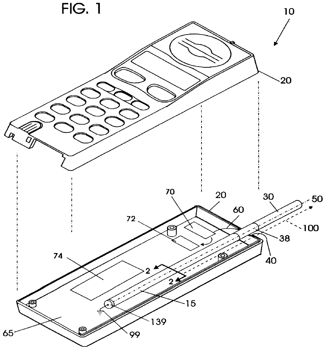
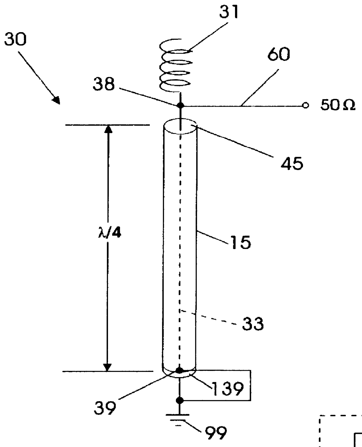
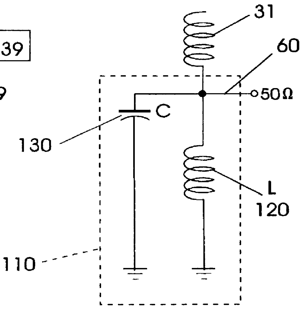
In the application, certain terms have been used to describe the positional relationships of certain of the features. As used herein, the term "longitudinal" and derivatives thereof refer to the general direction defined by the longitudinal axis of the radiotelephone housing including that associated with an antenna that extends upwardly and downwardly between opposing top and bottom ends of the radiotelephone when held in the hand of a user. As used herein, the terms "outer", "outward", "lateral" and derivatives thereof refer to the direction defined by a vector originating at the longitudina...


PUM


Abstract

Shields for radiotelephones with a retractable antenna include a conductive tubular antenna guide operably associated with an electronic ground, and preferably configured to form an inductor or capacitor in a matching circuit operable when the antenna is in the retracted position. Associated methods include directing RF radiation produced by the antenna positioned internal to the radiotelephone along a longitudinal exit path out of the radiotelephone.

Description

The present invention relates to telephones, and more particularly relates to shielding used for minimizing interference between components in telephones with retractable antennas.Many radiotelephones employ retractable antennas, i.e., antennas which are extendable and retractable out of the radiotelephone housing. The retractable antennas are electrically connected to a signal processing circuit positioned on an internally disposed printed circuit board. Unfortunately, the close proximity of the retracted antenna to certain electronic components in the radiotelephone housing can cause a variety of operational problems. For example, errant noises or radiated energy can enter the receiver and degrade the performance of the radiotelephone. Further, the close proximity of a user's hand to the retracted antenna can affect the radiation pattern of the radiotelephone and cause undesirable de-tuning effects.In order to optimally operate, the signal processing circuit and the antenna should...

Claims


Application Information

Patent Timeline
Patent Type & Authority Patents(United States)
IPC IPC(8): H01Q1/52H01Q1/00H01Q1/24H01Q9/36
CPCH01Q1/526H01Q1/244H01Q1/24
Inventor HOLSHOUSER, HOWARD E.SADLER, ROBERT A.
Owner UNWIRED PLANET
Why Eureka
Try Eureka