Gas collecting apparatus

a technology of gas collection apparatus and gas suction amount, which is applied in the direction of fluid pressure control, process and machine control, instruments, etc., can solve the problems of significant troublesome adjustment of flow rate or reading of gas suction amount, and the influence of ammonia gas generated from concrete or paint on the living environment, so as to reduce the size of the system, the effect of simple operation

Inactive Publication Date: 2000-10-31
OBAYASHI CORP
View PDF24 Cites 27 Cited by
  • Summary
  • Abstract
  • Description
  • Claims
  • Application Information

AI Technical Summary

Benefits of technology

It is an object of the present invention to provide a gas collecting system which can implement analysis of gas concentration of an inspection objective gas at high precision with simple operation, with achieving downsizing of the system.

Problems solved by technology

In the recent years, in dwelling houses or so forth employing various newly developed building materials, such as laminated plywood and the like, it has been pointed out that toxic gas of volatile organic compound, such as formic aldehyde and the like, discharged from the newly developed building materials, and such gas should have harmful influence on a living environment.
On the other hand, ammonia gas generated from a concrete or paint may promote degradation of exhibits in art museums and museums, or may be a cause of generation of faulty products in a clean room, such as semiconductor manufacturing factories and so forth.
Therefore, in the conventional gas collecting system, it is significantly troublesome for adjustment of flow rate or reading of a gas suction amount.
In conjunction therewith, the gas volumeter is precision mechanical equipment, and thus is required sufficient attention in handing for expensiveness and sufficient level of skill.
Also, an equipment and material for collection becomes large scale to cause difficulty in transportation of the equipment and material and in movement among inspection sites to make it troublesome for installation and adjustment to make gas collecting operation cumbersome.
However, in this method, it is required to cut a testing piece from the material to be inspected.
Therefore, it is not possible to perform inspection for the building completely constructed to limit range of application.

Method used


Image

  • Gas collecting apparatus
  • Gas collecting apparatus
  • Gas collecting apparatus

Examples


first embodiment

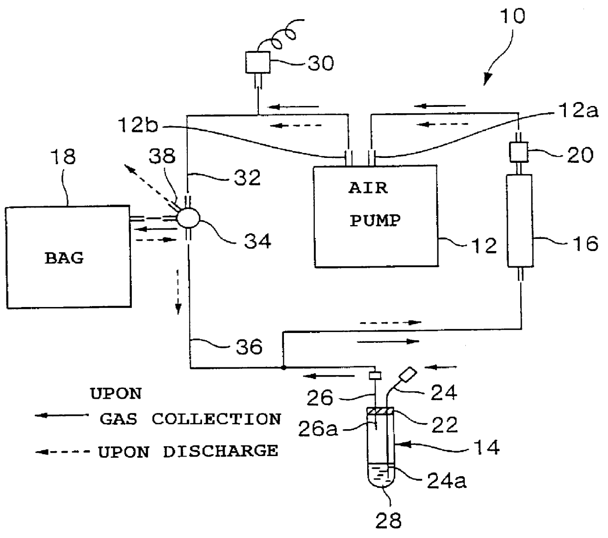
a gas collecting system according to the present invention basically includes a portable air pump 12 which is driven by a portable battery to suck a gas in an inspection objective space, an impinger 14 as a collecting vessel, in which a collecting liquid 28 for collecting an inspection objective gas from the foregoing gas is filled, a tube 24 having one end connected to the impinger 14 and the other end communicated with the foregoing inspection objective space for serving as an induction flow passage for introducing the foregoing gas into the impinger 14, a tube 26 having one end connected to the foregoing impinger 14 and the other end connected to a suction port 12a of the foregoing air pump 12 for serving as a suction flow passage introducing the foregoing gas into the air pump 12, a bag 18 connected to a discharge port 12b of the air pump 12 and accumulating the foregoing gas discharged from the air pump 12 for serving as a storage body operating as a volumeter, a drying agent t...

second embodiment

The second embodiment is directed to a type for sucking the gas into the casing 82 and simultaneously supplying the reference gas to the inspection object space sealed by the casing 82. While the construction of the downstream side from the impinger 14 is similar to that of the first embodiment, the construction on the upstream side of the impinger 14 is characteristic. Thus, only the characteristic portion is discussed.

As shown in FIG. 11, the shown embodiment of the gas collecting system 10 includes the casing 82 formed in hemispherical form in a predetermined thickness with a transparent material. In the casing 82, the supply port 86 for taking the purified air as the reference gas into the casing 82, and the sampling port 84 supplying the gas in the casing 82, in which the inspection objective gas is admixed, into the gas collecting system 10 constructed as illustrated in FIG. 1, are provided in opposed positions. The air pump 12 is designed to forcedly suck the gas within the c...

third embodiment

The third embodiment is the type that the gas within the casing 96 is sucked with maintaining the gas pressure within the inspection objective space closed by the casing 96. Similarly to the second embodiment, in the shown embodiment, while the construction on the downstream side of the impinger 14 is the same as that of the first embodiment, the construction on the upstream side of the impinger 14 is characteristic. Therefore, discussion will be given only for the characteristic portion.

For simplification of disclosure, first, FIG. 13 shows the case, in which only first envelope 100 is provided, and FIG. 14 shows the case where the second envelope 104 is additionally used.

As shown in FIG. 13, the shown embodiment of the gas collecting system 10b has the casing 96 for collecting the inspection objective gas discharged from the inspection object 80 by covering the inspection object 80 in the gas-tight condition. The gas containing the inspection objective gas, within the casing 96 is...


PUM

PropertyMeasurementUnit
widthaaaaaaaaaa
depthaaaaaaaaaa
depthaaaaaaaaaa

Abstract

PCT No. PCT/JP97/04118 Sec. 371 Date Apr. 5, 1999 Sec. 102(e) Date Apr. 5, 1999 PCT Filed Nov. 12, 1997 PCT Pub. No. WO98/22794 PCT Pub. Date May 28, 1998The present invention relates to a gas collecting system collecting an inspection objective gas, such as a toxic gas discharged into an ambient air, and particularly to a gas collecting system which can achieve down-sizing of the system and permit implementation of analysis of gas concentration of the inspection objective gas at high precision with simple operation.

Description

The present invention relates to a gas collecting system or collecting an inspection objective gas, such as toxic gas or the like, discharged into ambient air, and analyzing concentration of the collected inspection objective gas. More specifically, the invention relates to a gas collecting system which can implement an analysis of gas concentration of an inspection objective gas at high precision with simple operation with achieving downsizing of the system.In the recent years, in dwelling houses or so forth employing various newly developed building materials, such as laminated plywood and the like, it has been pointed out that toxic gas of volatile organic compound, such as formic aldehyde and the like, discharged from the newly developed building materials, and such gas should have harmful influence on a living environment. On the other hand, ammonia gas generated from a concrete or paint may promote degradation of exhibits in art museums and museums, or may be a cause of genera...

Claims


Application Information

Patent Timeline
Patent Type & Authority Patents(United States)
IPC IPC(8): G01N1/22G01N33/00G01N1/24
CPCG01N1/2273G01N33/0011G01N1/24Y10T436/25875G01N2001/2217G01N2001/241
Inventor KAWACHI, TAKESHIMORIYA, MASAHIROSATO, YASUE
Owner OBAYASHI CORP
Why Eureka
Try Eureka