Individual cylinder fuel control having adaptive transport delay index

a technology of individual cylinders and fuel control, which is applied in the direction of electric control, fuel injection control, machines/engines, etc., can solve the problems of difficult to correlate sensor readings with giver cylinders, inconvenient computation, and inability to accurately compare both approaches, so as to achieve high throughput requirements

Inactive Publication Date: 2000-11-21
DELPHI TECH IP LTD
View PDF6 Cites 52 Cited by
  • Summary
  • Abstract
  • Description
  • Claims
  • Application Information

AI Technical Summary

Benefits of technology

With either embodiment, the control of the invention eliminates the drawbacks of previously known controls, such as high through-put requirements or the expense of multiple sensors, and at the same time, adapts to changes that occur over time due to component degradation and variation and changes in engine hardware.

Problems solved by technology

Some systems utilize a single oxygen sensor, but variations in the transport delay time between a cylinder exhaust port and the oxygen sensor make it difficult to correlate the sensor readings with a giver cylinder.
The computation approach is often impractical due to through-put requirements, and both approaches suffer inaccuracy due to component variation (such as injector performance variations) and degradation over time.
Further, neither approach can adapt to engine hardware changes, such as installation of a different exhaust manifold or re-location of the oxygen sensor.

Method used


Image

  • Individual cylinder fuel control having adaptive transport delay index
  • Individual cylinder fuel control having adaptive transport delay index
  • Individual cylinder fuel control having adaptive transport delay index

Examples


Embodiment Construction

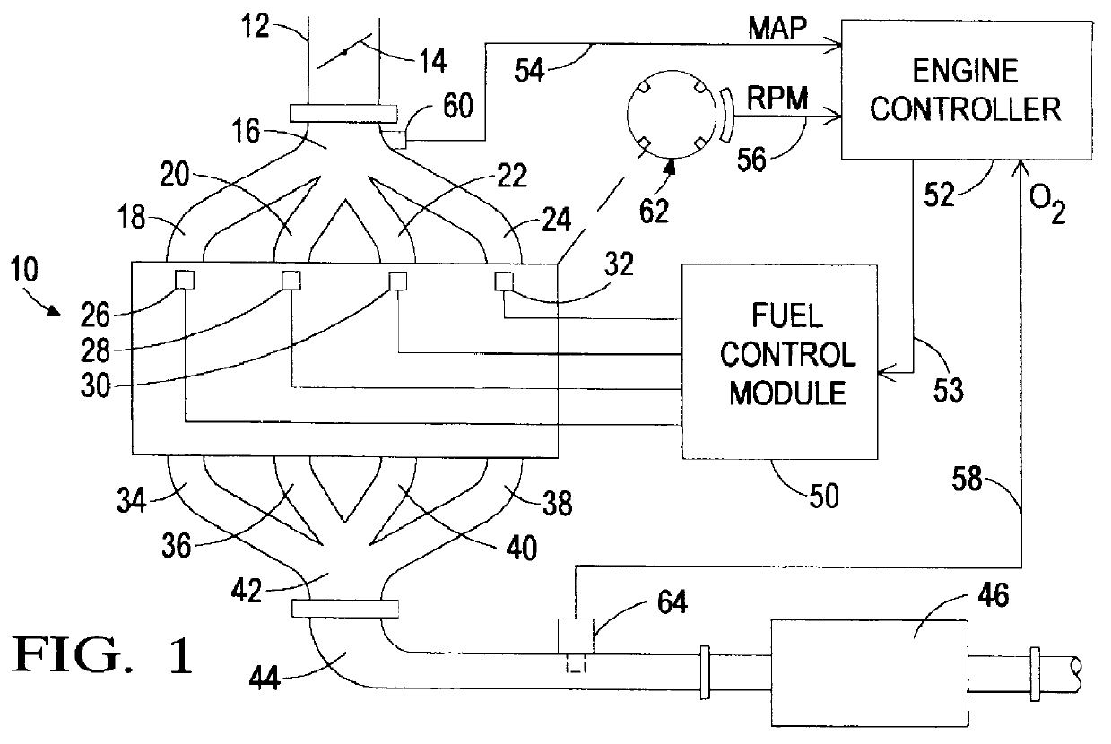
Referring to the drawings, and particularly to FIG. 1, the reference numeral 10 generally designates an automotive four-cylinder internal combustion engine. Engine 10 receives intake air through an intake passage 12 that is variably restricted by a moveable throttle valve 14. Downstream of throttle valve 14, the intake air enters an intake manifold 16 for distribution to the individual engine cylinders (not shown) via a plurality of intake runners 18-24. The fuel injectors 26-32 are positioned to deliver a predetermined determined quantity of fuel to each intake runner 18-24 for combination with the intake air and admission to respective engine cylinders for combustion therein. The combustion products from each cylinder are exhausted into respective exhaust runners 34-40 of an exhaust manifold 42, and combined in an exhaust pipe 44, which in turn, is coupled to a catalytic converter 46 for emission control purposes.

The fuel injectors 26-32 are electrically activated by a fuel contro...


PUM


Abstract

An improved individual cylinder fuel control method based on sampled readings of a single oxygen sensor responsive to the combined exhaust gas flow of several engine cylinders. The oxygen sensor output is sampled in synchronism with the engine firing events, a stored non-volatile table of offset values is used to correlate the sampled oxygen sensor values with individual engine cylinders, and a new offset value is determined and stored in place of a current offset value when the current offset value fails to reduce a measure of air / fuel ratio maldistribution among the engine cylinders. In systems having an oxygen sensor of the switching type, the measure of air / fuel ratio maldistribution is determined by filtering and integrating the oxygen sensor signal, and the new offset value is determined by repeatedly incrementing the stored offset value, and fueling the individual cylinders of the engine based on the incremented offset value, until the measure of air-fuel ratio maldistribution decreases. In systems having a wide-range oxygen sensor, the measure of air / fuel ratio maldistribution is determined by summing the air / fuel ratio errors identified by the sensor, and the new offset value is determined by alternately toggling a selected cylinder rich and lean, and sampling the oxygen sensor signal to identify the selected cylinder. Either way, the control adapts the stored offset values for changes that occur over time due to component degradation and variation and changes in engine hardware.

Description

TECHNICAL FIELDThis invention relates to fuel control of a multi-cylinder internal combustion engine, and more particularly a control for carrying out individual cylinder fuel control with a single exhaust gas oxygen sensor.BACKGROUND OF THE INVENTIONEffective emission control of internal combustion engine exhaust gases with a catalytic converter requires precise control of the air / fuel ratio supplied to the engine cylinders. For this purpose, it is customary to install an oxygen sensor in the engine exhaust pipe, and to use the sensor output as a feedback signal for closed-loop fuel control. Commonly, the exhaust gases of several cylinders are combined in an exhaust manifold, with a single oxygen sensor is positioned near the outlet of the exhaust manifold, and an average reading of the oxygen sensor is used as a common feedback signal for controlling the fuel supplied to each of the several cylinders.The above-described control technique assumes a uniform air and fuel distribution...

Claims


Application Information

Patent Timeline
Patent Type & Authority Patents(United States)
IPC IPC(8): F02D41/14F02D41/34F02D41/00
CPCF02D41/0085F02D41/1454F02D41/2474F02D41/2454F02D41/1456
Inventor KAINZ, JEFF LEON
Owner DELPHI TECH IP LTD
Why Eureka
Try Eureka