Method and apparatus for level decision and optical receiver using same

Inactive Publication Date: 2000-11-21
LAPIS SEMICON CO LTD
View PDF3 Cites 87 Cited by
  • Summary
  • Abstract
  • Description
  • Claims
  • Application Information

AI Technical Summary

Benefits of technology

Accordingly, an object of the invention is to provide method and apparatus for level decision which is easily designed t

Problems solved by technology

According to a conventional level decision circuit, however, in order to maintain a high transmission rate, the structu

Method used


Image

  • Method and apparatus for level decision and optical receiver using same
  • Method and apparatus for level decision and optical receiver using same
  • Method and apparatus for level decision and optical receiver using same

Examples


Embodiment Construction

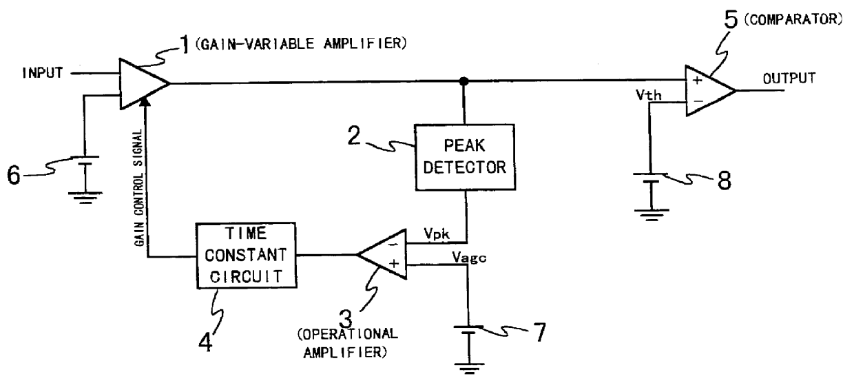
For better understanding of the invention, background technology is first described. FIG. 1 shows a conventional level decision circuit using an AGC (Automatic Gain Control) scheme, which is generally mounted in an optical receiver. The level decision circuit includes a gain-variable amplifier 1, which receives an input signal and amplifies it in accordance with a controlled gain level. The gain-variable amplifier 1 is connected at an output terminal to a peak detector 2, which detects a peak voltage "Vpk" of the output signal of the gain-variable amplifier 1, and to an input terminal of a comparator 5. The peak detector 2 is connected at an output terminal to an input terminal of an operational amplifier 3, of which the other input terminal is connected to a control voltage source 7.

The operational amplifier 3 compares the peak voltage "Vpk" and a control voltage "Vagc," supplied from the control voltage source 7, to generate a gain control signal so that the peak voltage "Vpk" app...


PUM


Abstract

In a method for deciding the level of an input signal, positive and negative signals are provided in response to the input signal. A peak of the positive signal is detected to provide a positive-peak value. A peak of the negative signal is detected to provide a negative-peak value. The positive signal and the negative-peak value are combined to provide a first combination signal. The negative signal and the positive-peak value are combined to provide a second combination signal. The first and second combination signals are compared to provide an output signal of zero or one.

Description

This application claims the priority of Applications No. H09-044073, filed Feb. 27, 1997 and H08-262624 filed Oct. 3, 1996 both in Japan. The subject matter of each application is incorporated herein by reference.The present invention relates to a signal transmission system, and more particularly to a level decision circuit used in a signal receiver.For realizing an all-optical subscriber network, the PDS (Passive Double Star) technique has been considered to be useful and important, in which variety types of multiplexing schemes are used. In a PDS subscriber network system, it is required to use an optical receiver which performs AGC (Automatic Gain Control) or ATC (Automatic Threshold Control) to process burst mode optical signals. Such an optical receiver includes a level decision circuit, which decides the level of the input signal to generate a digital output signal of zero or one.In a PON (Passive Optical Network) system, burst mode signals are transmitted from a transmitter t...

Claims


Application Information

Patent Timeline
IPC IPC(8): H04B10/158H04B10/152H03F3/45H04B10/07H03K5/08H04B10/272H04B10/40H04B10/50H04B10/60H04L25/03
CPCH04B10/695
Inventor KIKUCHI, OSAMU
Owner LAPIS SEMICON CO LTD
Why Eureka
Try Eureka