Fuel filter with return path for reducing electrical charge buildup

a fuel filter and return path technology, which is applied in the direction of filtration separation, positive displacement liquid engine, separation process, etc., can solve the problems of electric charge not readily building up on the surface of the filter case, possibility of generating a spark between the fuel tank and the filter case, and easy accumulation of electric charg

Inactive Publication Date: 2000-12-05
AISAN IND CO LTD
View PDF16 Cites 19 Cited by
  • Summary
  • Abstract
  • Description
  • Claims
  • Application Information

AI Technical Summary

Problems solved by technology

The electric charge does not readily build up on the surface of the filter case when the filter case is immersed in the fuel reservoir in the fuel tank.
However, electric charge tends to readily build up as the amount of fuel remaining in the tank becomes less.
When electric charge builds up on the surface of the filter case, there is a possibility of generating a spark between the fuel tank and the filter case.
However, when this technique is used for a fuel filter that is inserted into the fuel tank, provision of the conductive path between the filter case and the fuel tank complicates the device construction and decreases assembling efficiency.
However, these measures increase manufacturing costs and decrease assembling efficiency.

Method used


Image

  • Fuel filter with return path for reducing electrical charge buildup
  • Fuel filter with return path for reducing electrical charge buildup
  • Fuel filter with return path for reducing electrical charge buildup

Examples


embodiment 1

A first embodiment of the present invention will now be described with reference to FIGS. 1 to 3.

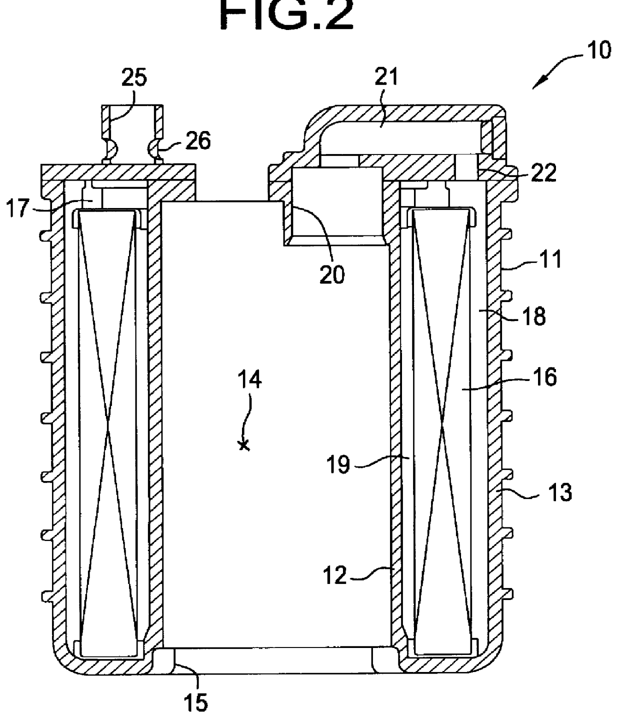
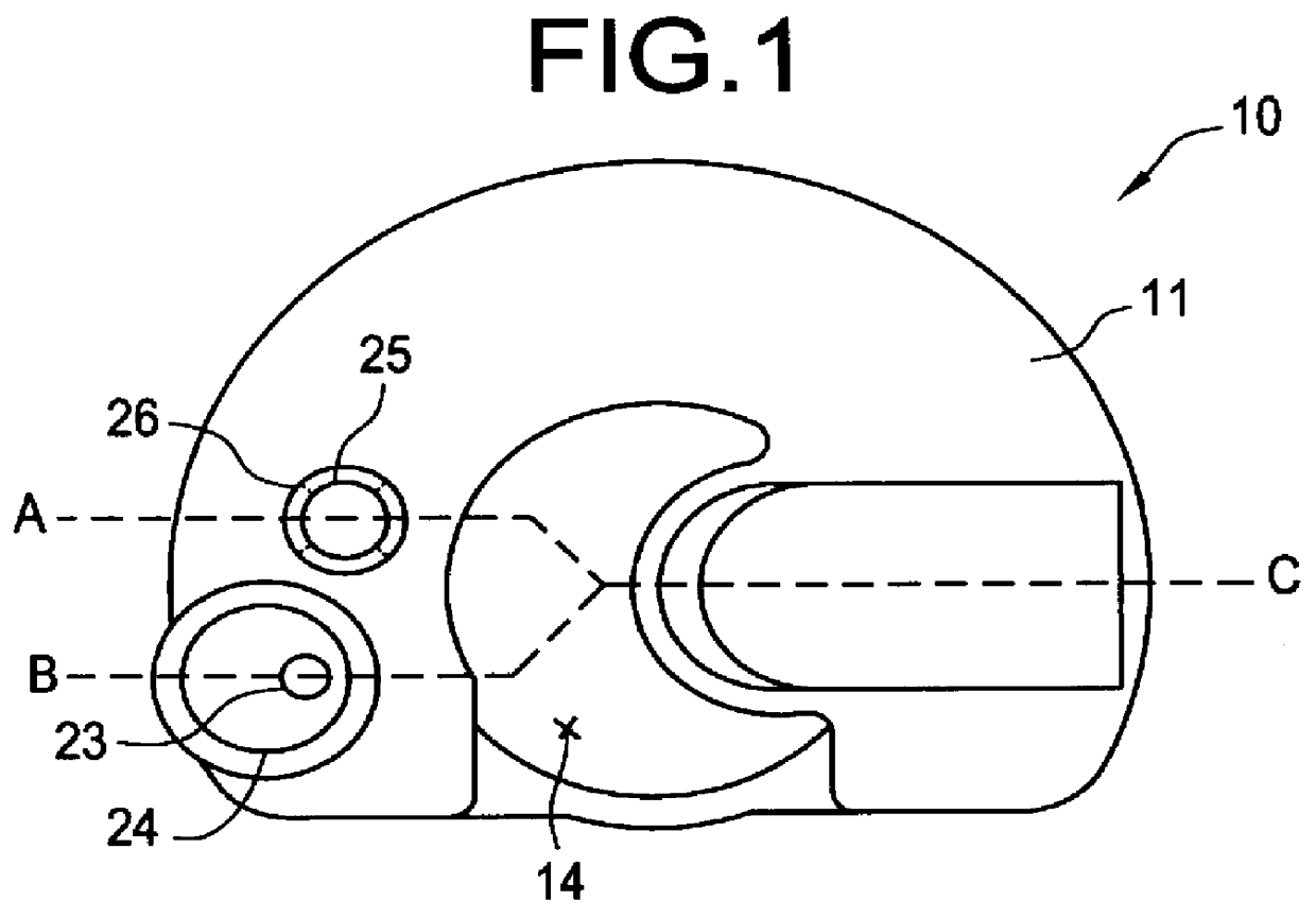
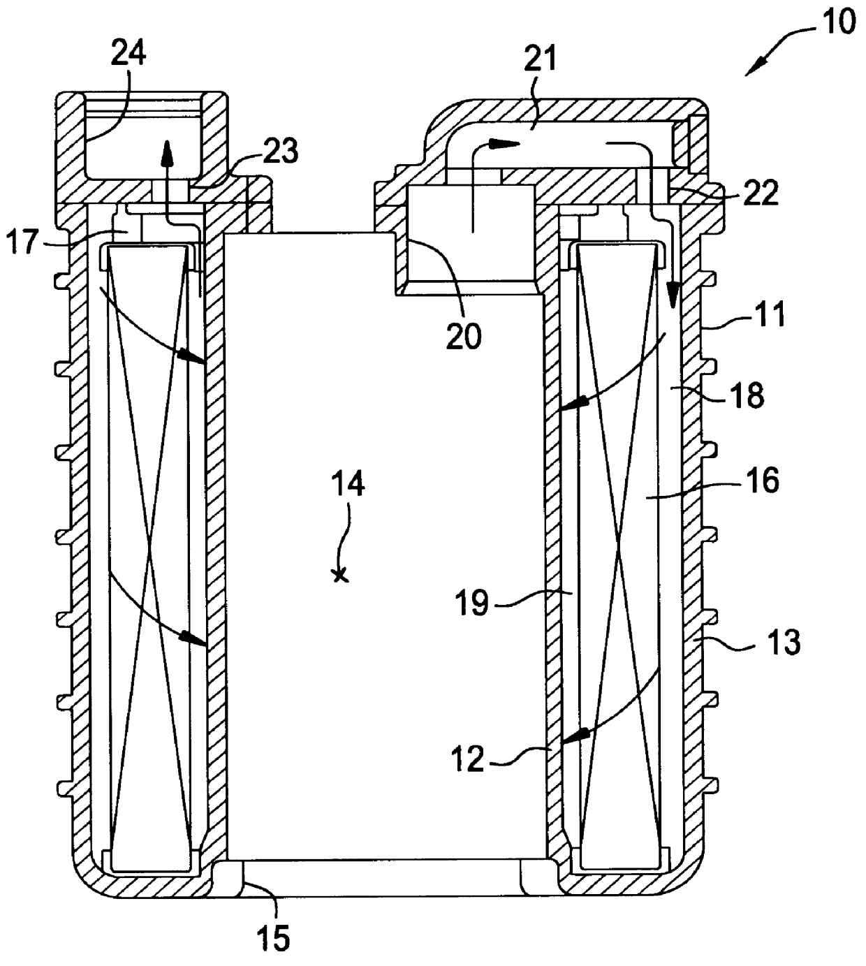
As shown in FIGS. 1 to 3, a fuel filter 10 comprises a filter case 11 made of synthetic resin or other like material. The filter case includes an inner peripheral wall 12 and an outer peripheral wall 13. The inner peripheral wall 12 has a fuel pump inserting portion 14 with a port 15 for inserting a fuel pump.

Although the filter case 11 is formed into a D-shape in this embodiment, cylindrical or other shapes also may be used.

Between the inner peripheral wall 12 and the outer peripheral wall 13, a filter element 16 is provided to remove impurities in fuel delivered from the fuel pump. The filter element 16 of this embodiment is a filter medium sheet which is pleated and curved to have a C-shaped cross-section, although other materials or shapes may be used therefor.

The filter element 16 is mounted in the filter case 11 via a sealing member 17 such that a fuel inlet chamber and a fuel outl...

embodiment 2

In the first embodiment, the fuel return passage is provided on the upper surface of the filter case. However, the return path also can be provided along the outside surface of the filter case. Referring now to FIGS. 6 and 7, a fuel filter of this type will be described according to a second embodiment of the present invention.

As shown in FIGS. 6 and 7, a filter case 81 for a fuel filter 80 is provided with a return path 85 beginning at the top surface of the filter case 81 and extending along the outside peripheral surface thereof. The return path 85 has a circular cross section at the top of the filter case 81 and may be positioned opposite to or may be connectable to a discharge port of a pressure regulator. A portion of the return path 85 along the outside peripheral surface of the filter case 81 is formed to have a semicircular cross section. On a lower part of the side wall of the return path 85, a discharge port 86 is provided for discharging return fuel into the fuel reservo...

embodiment 3

Referring now to FIGS. 8 to 10, a filter of a third embodiment of the present invention will be described.

As shown in FIGS. 8 to 10, a return path 95 is provided on the top surface of a filter case 91 of a fuel filter 90 so that the return fuel discharged from the pressure regulator may be fed along the top surface of the filter case 91. Branch paths 96 are branched from suitable positions along the return path 95.

Preferably, the return path 95 and the branch paths 96 are formed of synthetic resin or like materials integrally with the filter case 91.

In the fuel filter of the third embodiment, the return fuel discharged from the pressure regulator 60 is fed by the return path 95 along the top surface of the filter case 91, flows through the branch paths 96 branched from the suitable positions along the return path 95, and is returned to the fuel reservoir along the outside peripheral surface (inner outside periphery and outer outside periphery) of the filter case 91. Electric charge ...


PUM

PropertyMeasurementUnit
electric chargeaaaaaaaaaa
pressureaaaaaaaaaa
conductiveaaaaaaaaaa

Abstract

PCT No. PCT/JP97/02517 Sec. 371 Date Jul. 25, 1998 Sec. 102(e) Date Feb. 25, 1998 PCT Filed Jul. 22, 1997 PCT Pub. No. WO98/03787 PCT Pub. Date Jan. 29, 1998A fuel filter (10) has a filter case (11), and a return path (25) is provided on the upper surface of the filter case (11). Return fuel discharged from a pressure regulator is supplied to the return path (25). The return path (25) having a closed lower end is provided with branch paths (26). The return fuel supplied to the return path (25) passes through the branch paths (26) and flows down into fuel reservoir along the outside peripheral surface of the filter case (11). Electrical charge on the surface of the filter case (11) is reduced when the return fuel flows along the outside peripheral surface of the filter case (11). Kinetic energy of the return fuel is reduced by the energy absorbing effect of the return path (25), the energy distributing effect of the branch paths (26), and the energy absorbing effect when the return fuel flows down along the outside peripheral surface of the filter case. Thus, fuel return sound waves from the returning fuel dropping into the fuel reservoir are reduced.

Description

This invention relates to a fuel filter for filtering impurities from fuel delivered from a fuel tank by a fuel pump.TECHNICAL BACKGROUNDAs disclosed in Japanese Laid-Open Utility Model Publication No. 4-109465, it has been well known that a fuel pump and a fuel filter for filtering impurities from fuel delivered from a fuel tank by the fuel pump can be integrally formed to be inserted into the fuel tank.Further, it also has been well known that a pump module constructed by assembling a fuel pump and a fuel filter together can be inserted into a fuel tank.When the fuel passes through the fuel filter, a surface of a filter case becomes electrically charged due to frictional electrification between the fuel and the fuel filter and due to fluid electrification between the fuel and the filter case. The magnitude of the electric charge or electrifying potential of the fuel case is proportional to the fuel flow rate through the fuel filter.The electric charge does not readily build up on ...

Claims


Application Information

Patent Timeline
Patent Type & Authority Patents(United States)
IPC IPC(8): B01D35/027B01D35/00F02M37/08F02M37/22F02M37/10F02M37/44F02M37/46F02M37/50
CPCB01D35/027F02M37/10F02M37/22B01D35/26B01D2201/50F02M2037/225F02M37/44F02M37/50F02M37/46
Inventor UEDA, HIRONORINAGAI, TAKASHISUZUKI, NOBUOHORIUCHI, TADAO
Owner AISAN IND CO LTD
Why Eureka
Try Eureka