Integrated heatsink and heatpipe

a heatpipe and heatsink technology, applied in the direction of insulated conductors, semiconductor/solid-state device details, cables, etc., can solve the problems of large thin heatsinks and heatpipes that have not found universal application, and achieve efficient heat transfer, improve heatsinks, and improve heatsinks.

Inactive Publication Date: 2000-12-19
GLOBALFOUNDRIES INC
View PDF16 Cites 115 Cited by
  • Summary
  • Abstract
  • Description
  • Claims
  • Application Information

AI Technical Summary

Benefits of technology

It is an object of the present invention to efficiently transfer heat from a heat source to all portions of a heatsink for more efficient

Problems solved by technology

It has been found, however, that when cooling requirements are stringent and available physical space is constrained in the height or z direction, a large

Method used


Image

  • Integrated heatsink and heatpipe
  • Integrated heatsink and heatpipe
  • Integrated heatsink and heatpipe

Examples


Embodiment Construction

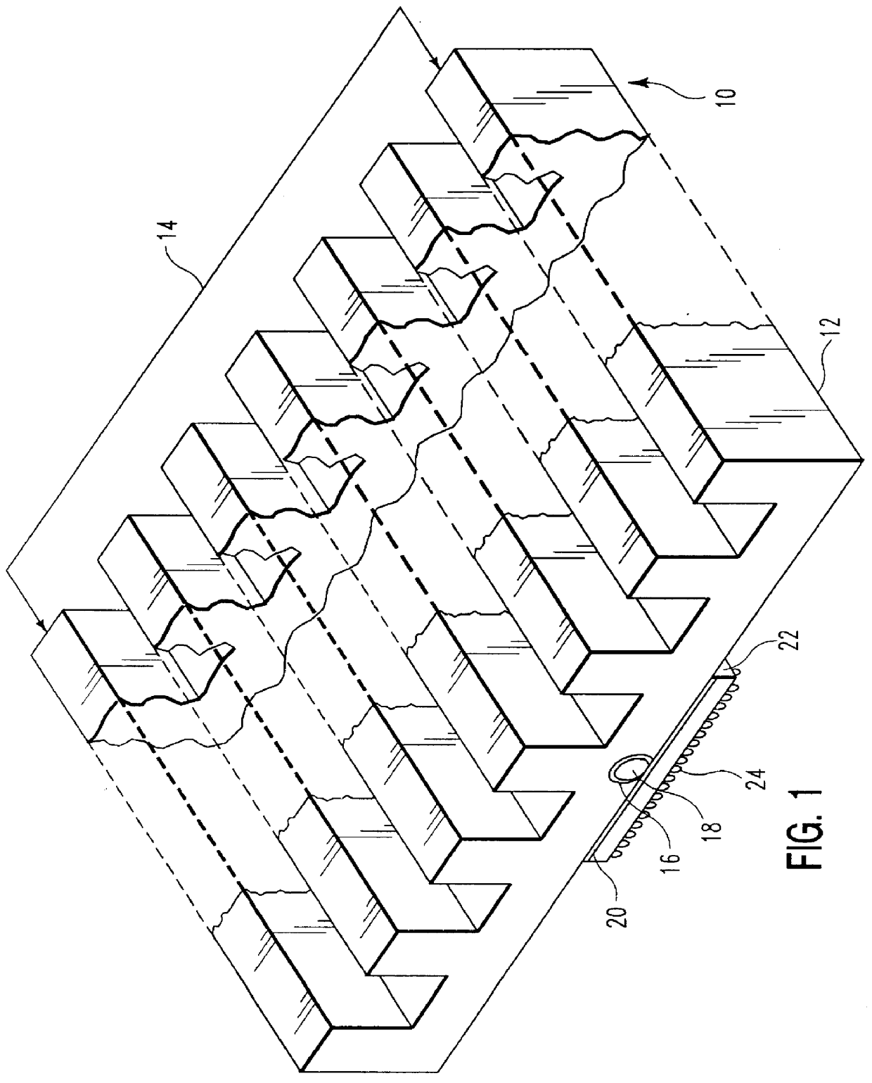
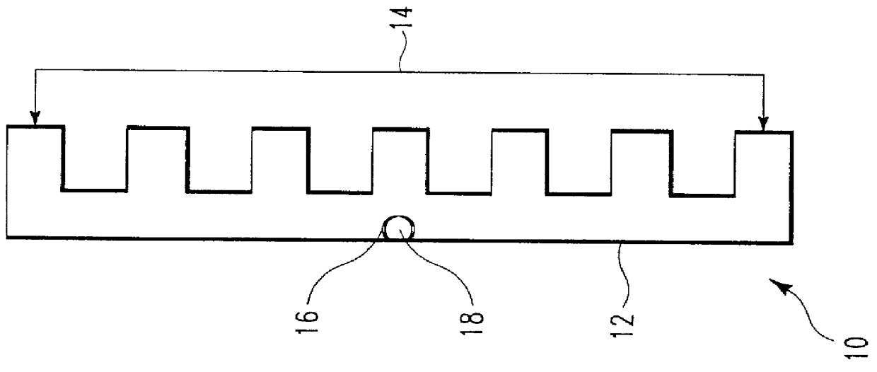
With more specific regard now to FIG. 1, there is shown a heatsink 10 having a base 12 and fins 14 for heat dissipation. Within the base 12 a groove 16 is formed providing a channel within which a heatpipe 18 is located. In this embodiment the heatsink 10 and heatpipe 18 are attached by a thermal adhesive 20 to an electronic module 22 having pins 24 for connecting to a printed circuit board 26 (see FIG. 2). Electronic module 22 is a packaged integrated chip. It could also be an IC chip or discrete power component directly attached to heatsink 10 and heatpipe 18.

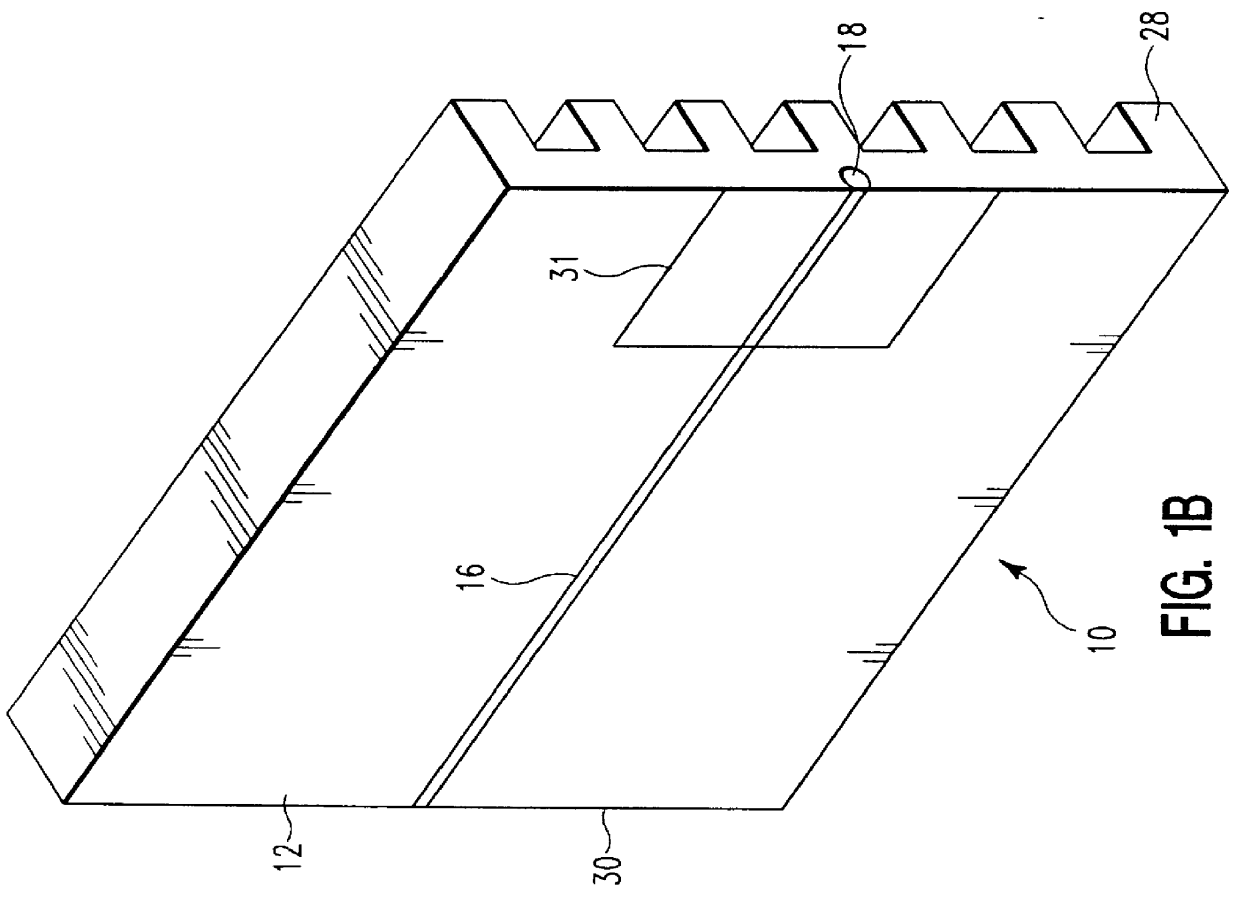
As seen in FIG. 1A the groove 16 in the base 12 is sized to allow the heatpipe 18 to contact the module 22 (FIG. 1) along the plane of base 12 via the adhesive layer 20 (FIG. 1). FIG. 1B shows the groove 16, extending from edge 28 to edge 30 of the heatsink 10. Area 31 is the area of contact between heatsink 16 and module 22. Heatpipe 18 transfers heat within heatsink 10 from area 31 to distant portions of heatsink 10 to redu...


PUM


Abstract

A heatsink mounted to an electronic device having an area substantially greater than that of the device includes a heatpipe in the heatsink for transferring heat within the heatsink to reduce thermal gradients therein.

Description

This invention relates to a multimode heatsink for an electronic module which mounts to a printed circuit board.BACKGROUND OF INVENTIONPresent day electronic devices require special provisions for removing heat. Some prior art examples include adding heatsinks and other thermally conductive structures to the electronic device. It is also known to have air cooling for structures containing electronic devices.More recently heatpipes have been employed to transfer heat from the device to a remote location where the heat is then removed by a heatsink, a fan, or any other appropriate device.The cooling requirement, available physical space for the cooling solution, cost of the solution and the reliability requirement of the solution help determine the type of external cooling solution. Where the reliability and the cost of the cooling solution are the most important criteria for an application, a heatsink is an ideal candidate. It has been found, however, that when cooling requirements a...

Claims


Application Information

Patent Timeline
IPC IPC(8): F28D15/02H01L23/34H01L23/427
CPCF28D15/0233H01L23/427H01L2924/0002H01L2924/00F28D15/0275
Inventor PATEL, JANAK G.
Owner GLOBALFOUNDRIES INC
Why Eureka
Try Eureka