Air conditioning condensation drainage system

a drainage system and air conditioner technology, applied in the direction of defrosting, heating types, domestic cooling apparatus, etc., can solve the problems of oxidizing the roof membrane, affecting the performance of the roof membrane, and increasing the detrimental effect of these materials on the roof membrane,

Inactive Publication Date: 2001-01-02
SACKIT
View PDF6 Cites 37 Cited by
  • Summary
  • Abstract
  • Description
  • Claims
  • Application Information

AI Technical Summary

Problems solved by technology

Moreover, as water evaporation occurs and a / c condensation continues to be added onto the roofing membrane, the concentration of chemicals and heavy metals will continuously increase thus increasing the detrimental effect of these materials to the roofing membrane.
It has been found that summer heat will actually turn the water flows and pools into boiling water which will literally oxidize the roofing membrane.
Extreme cold will freeze these water flows and pools causing fissures in the roof membrane surface.
Present methods of removing the a / c condensation from the roof surface are not effective.
It has been found with condensate drainage piping that the piping systems quickly become clogged with debris and algae that is present within the drainage system, especially when the a / c unit is situated in a humid environment.
As typically occurs in roofing systems, having condensate drain conduits, because of traffic, age, and constant clogging problems requiring significant maintenance effort and expense, personnel having the responsibility for building maintenance will eventually disconnect the condensate drainage pipes from the air conditioning units.
The eventual result is that the disconnected a / c drainage pipes will end up as debris that is present on the roof surface.
This disconnected piping debris obviously presents a hazard to workers engaged in roofing maintenance and repair and can be a cause of damage to the roofing membrane
While commercial buildings can be provided with internal a / c drain piping systems that extend throughout the building structure to conventional building drain lines, this method is seldom used.
Debris collected by the condensate of the a / c units will flow along with the condensate into the drain lines and in time will clog the lines.
The algae that builds up in all a / c drain lines also causes clogging of the lines.
In a relatively short time the drain lines will be sufficiently blocked that flow of condensate drainage will be blocked.
These systems are virtually always abandoned due to clogging because the drain lines, being located within the building structure are difficult to access and service or repair.
Even though the presence of a / c condensate on a roof membrane is known to cause damage to the roofing system, surface drainage is the method that is most often employed for condensate drainage.
In this case, persistent a / c condensation fluids are allowed to collect in certain areas on the roof membrane surface, causing extensive and accelerated roof membrane deterioration.

Method used


Image

  • Air conditioning condensation drainage system
  • Air conditioning condensation drainage system
  • Air conditioning condensation drainage system

Examples


Embodiment Construction

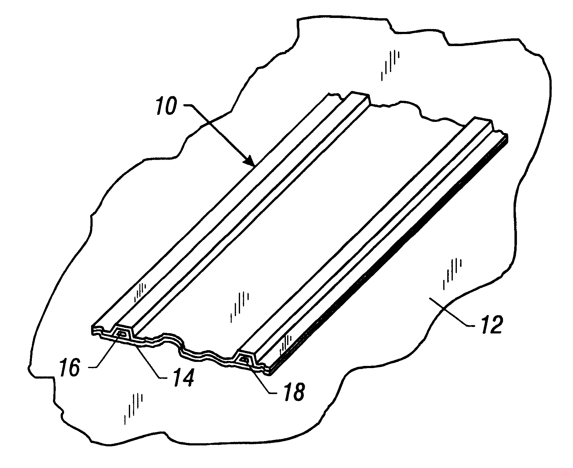
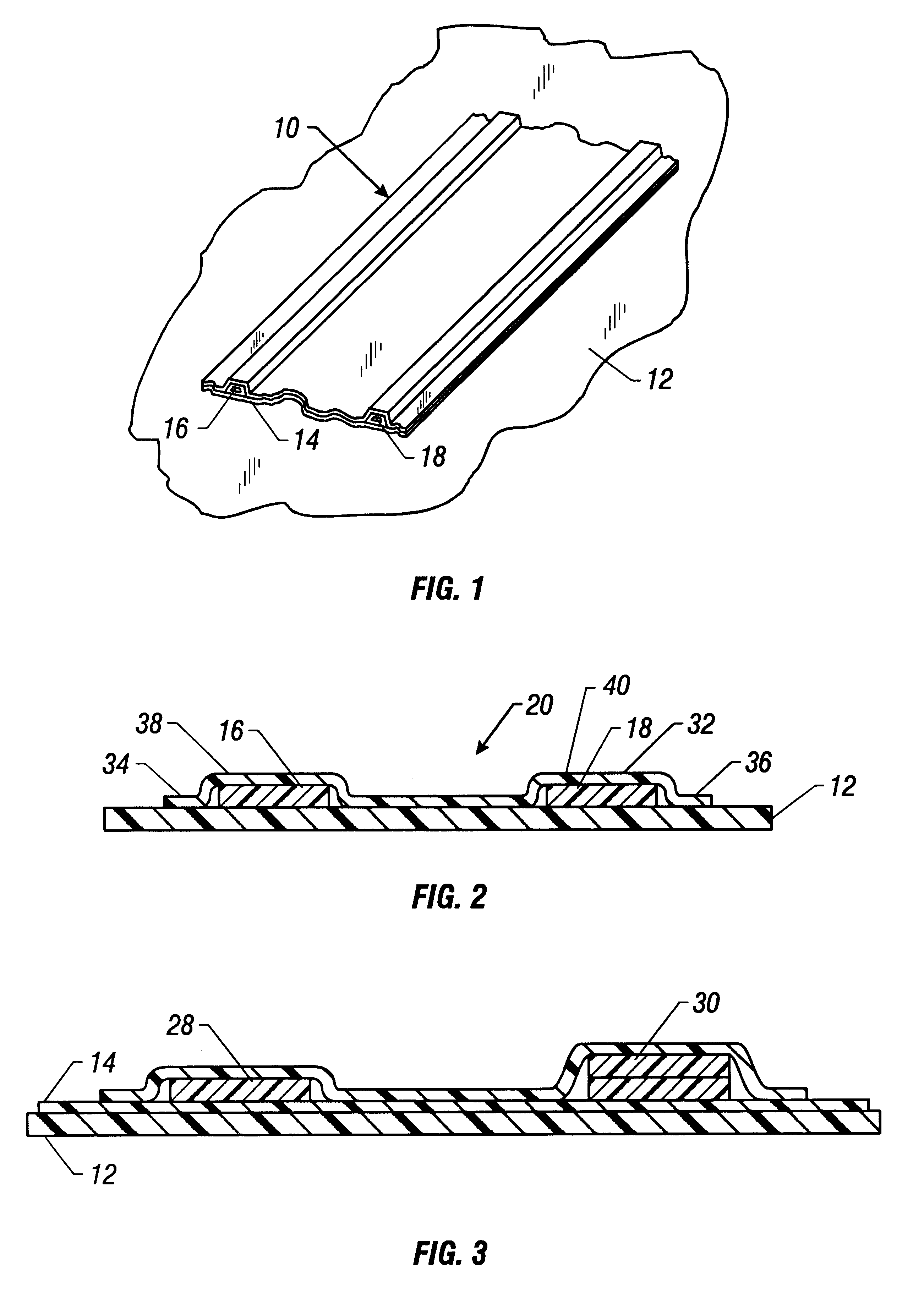
Referring now to the drawings and first to FIG. 1, an air-conditioning condensate drainage system constructed in accordance with the principles of the present invention and representing the preferred embodiment is shown generally at 10 and is shown in the figure as a partial strip of condensate drain structure which is shown to be mounted in any suitable fashion onto the roofing, membrane 12 of a building roofing system. The air-conditioning condensate drainage system of FIG. 2 is a sectional view of the drainage system structure shown in FIG. 1, differing only in the specific cross-sectional geometry of the ridge defining elements as will be explained in detail hereinbelow.

The air-conditioning condensate drainage system 10 comprises an isolation membrane 14 which is typically in the form of an elongate strip of material that is compatible with the membrane material of the roofing membrane 12. Typically, the isolation membrane will be constructed of a polymer material such as polyvi...


PUM


Abstract

An air-conditioning condensate drainage system for mounting to the roof membrane of the roof structure of buildings or for constructing directly onto the roof membrane of a building structure. The air-conditioning condensate drainage system has an isolation membrane having a bottom surface for assembly to a roof membrane. A pair of ridge structures are disposed in fixed relation with the isolation membrane and are disposed in spaced relation with one another and cooperate with the isolation membrane to define an air-conditioning condensate drainage channel between the spaced ridge structures. Each of the ridge structures has one or more ridge defining elements which is fixed to the isolation membrane and projects above the isolation membrane sufficiently to define a condensate drain channel therebetween. One or more upper membranes may be disposed in covering relation with the ridge defining elements and are conformed to suitable configuration by the ridge forming structures to define spaced condensate containment ridges. The upper membranes are also fixed to the upper surface of the isolation membrane to form an integral condensate drainage unit to conduct a/c drainage from a/c units to an in-roof mounted drain.

Description

1. Field of the InventionThe present invention relates generally to the compromise or deterioration of roofing membrane materials by the condensate from air conditioning systems that are mounted on or above the roofs of commercial buildings having what is typically referred to as a "flat roof". More particularly, the present invention concerns the provision of a roof mounted drain system for collecting air conditioning condensate and conducting it to a disposal drain and simultaneously isolating the roof membrane from contact by the air conditioning condensate. Even more specifically, the present invention concerns structure and materials for creating an nondestructive path over the surface of a roofing system, that will direct discharged air conditioning condensate from roof mounted air conditioning units to one or more in-roof drains or gutters for disposal and will serve to isolate the roof membrane from the condensate.2. Description of the Prior ArtRoofing membrane deterioration...

Claims


Application Information

Patent Timeline
Patent Type & Authority Patents(United States)
IPC IPC(8): F24F13/00F24F13/22F25D21/14F24F3/044
CPCF24F13/222F24F3/044F25D21/14F25D2321/146Y10S62/16
Inventor DUDLEY, WILLIAM E.DUTTON, C. ROSS
Owner SACKIT
Why Eureka
Try Eureka