
Discharge valve

a technology of discharge valve and compressor, which is applied in the direction of functional valve types, machines/engines, liquid fuel engines, etc., can solve the problems of strong tendency to backflow compressed gas from the system, reverse movement often generates objectionable noise or rumble, and further sources of objectionable noise, etc., to achieve the effect of extreme efficiency of operation

Inactive Publication Date: 2001-01-09
EMERSON CLIMATE TECH INC
View PDF26 Cites 72 Cited by
  • Summary
  • Abstract
  • Description
  • Claims
  • Application Information

AI Technical Summary

Benefits of technology

In order to limit such reverse rotation, prior art scroll compressors have incorporated ball type check valves at the point of connection between the outer shell and the discharge line. While such ball type check valves have been effective to limit back flow of compressed refrigerant, they have demonstrated a tendency to vibrate or chatter under certain flow conditions thus presenting a further source of objectionable noise. Also, in severe situations, the chattering may result in damage or destruction of the ball stop and / or seat. Additionally, the occasional discharge of liquid through such ball type check valves further increases the possibility of damage thereto.
Other prior art scroll compressors incorporate disc type check valve in the outlet from the outer shell which effectively prevents return flow of compressed gas from the refrigeration system and hence limits reverse orbital movement of the orbiting scroll member. Because reverse orbital movement is thus limited, the possibility of objectionable noise being generated thereby upon shut down of the compressor is greatly reduced. The disc type discharge valve does not require any biasing means but rather operates to create a pressure differential thereacross which moves the disc between seated and unseated positions. The disc type discharge valve provides an inexpensive, easily installed means to effectively resist reverse movement of the orbiting scroll. Further, because a relatively large stop surface area is provided extending around the periphery of the valve member, the possibility of damage from discharge of liquid therethrough is greatly reduced.

Problems solved by technology

However, when such compressors are shut down, either intentionally as a result of the demand being satisfied or unintentionally as a result of a power interruption, there is a strong tendency for backflow of compressed gas from the system in combination with high pressure gas contained in the chambers and / or discharge muffler to effect a reverse orbital movement of the orbiting scroll member and associated drive shaft.
This reverse movement often generates objectionable noise or rumble.
Further, in machines employing a single phase drive motor, it is possible for the compressor to begin running in the reverse direction should a moment a ry power failure be experienced.
While such ball type check valves have been effective to limit back flow of compressed refrigerant, they have demonstrated a tendency to vibrate or chatter under certain flow conditions thus presenting a further source of objectionable noise.
Also, in severe situations, the chattering may result in damage or destruction of the ball stop and / or seat.
Additionally, the occasional discharge of liquid through such ball type check valves further increases the possibility of damage thereto.
Both of these forming operations are relatively expensive leading to an increase in the manufacturing costs.

Method used


Image

  • Discharge valve
  • Discharge valve
  • Discharge valve

Examples


Embodiment Construction

The present invention is illustrated for exemplary purposes in conjunction with a hermetically sealed scroll compressor. It is to be understood that the present invention is not limited to a scroll compressor and that it is possible to use the disc type discharge valve assembly of the present invention on virtually any type of motor compressor or similar machine.

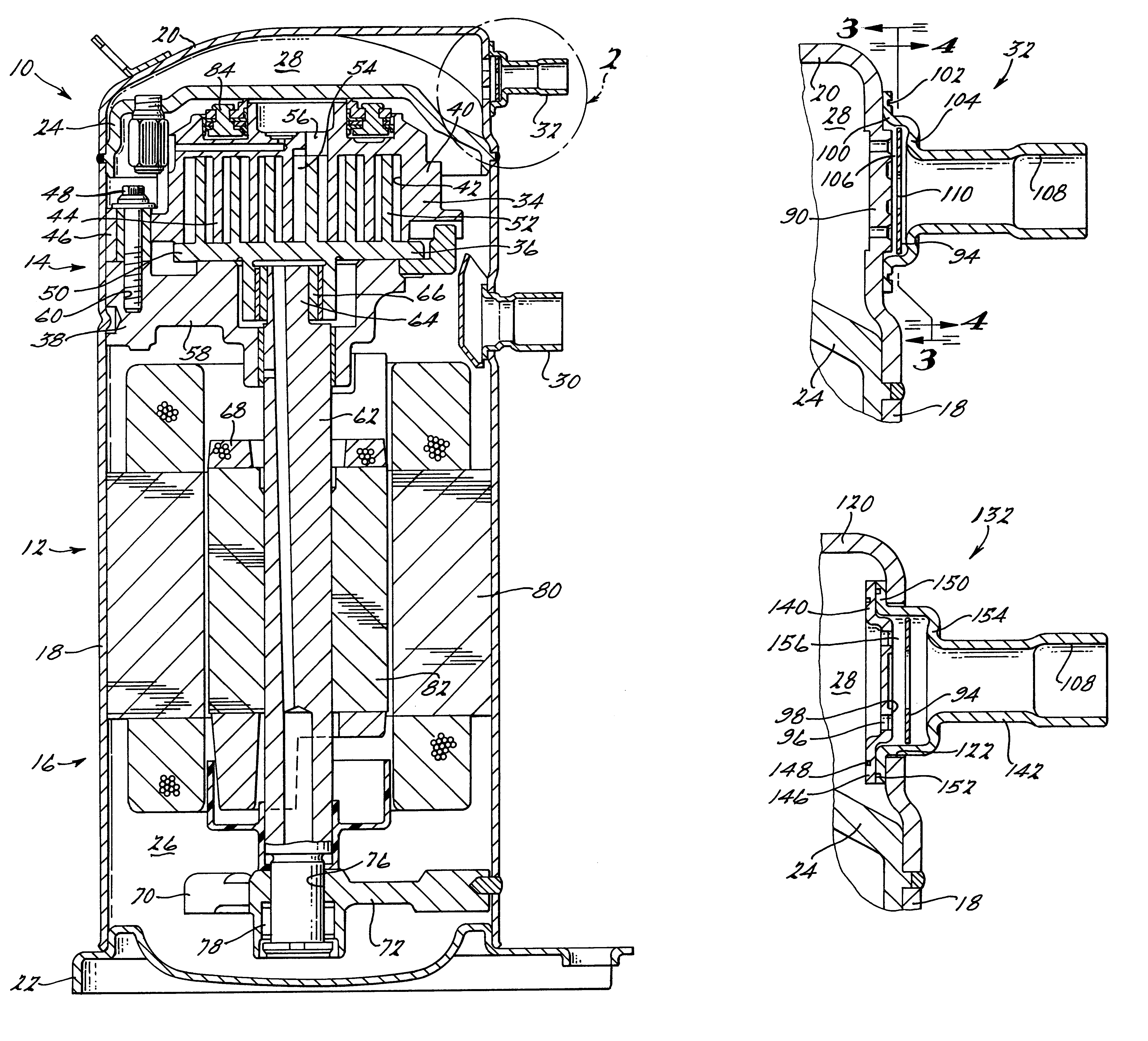
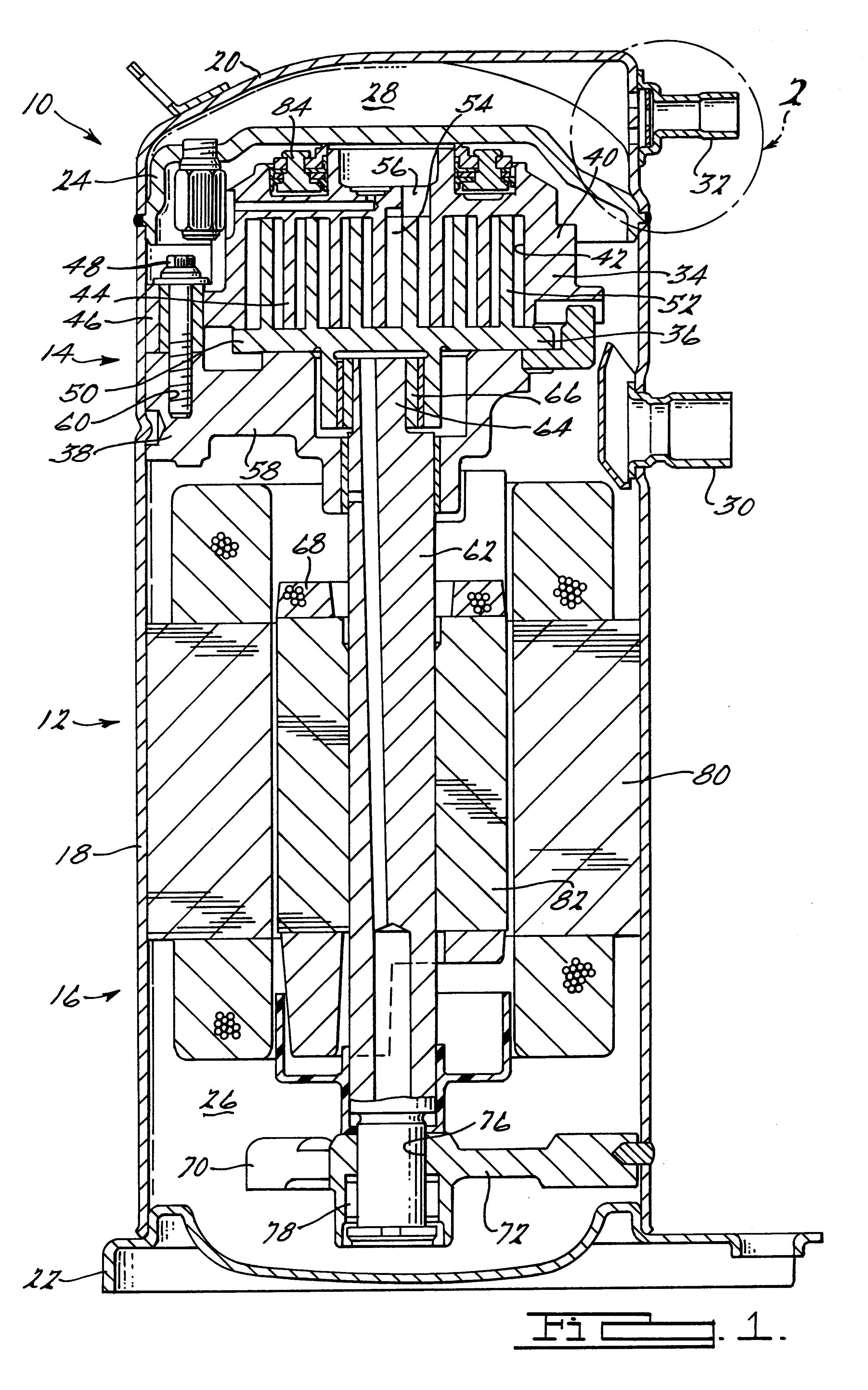
Referring now to the drawings in which like reference numerals designate like or corresponding parts throughout the several views, there is shown in FIG. 1, a scroll compressor including the disc type discharge valve assembly in accordance with the present invention which is designated generally by the reference numeral 10. Compressor 10 is comprised of a hermetic shell assembly 12, a compressor section 14 and a motor drive section 16. Hermetic shell assembly 12 is comprised of a lower shell 18, an upper cap 20, a bottom cover 22 and a partition plate 24. Bottom cover 22, lower shell 18, partition plate 24 and upper cap 20 a...


PUM


Abstract

A compressor assembly includes a shell which defines a discharge chamber. A discharge valve assembly is attached to the shell in communication with the discharge chamber. The discharge valve assembly includes a stamped or coined valve seat, a drawn tubular element and a stamped valve member. The stamping, drawing and coining operations used to manufacture the discharge valve assembly significantly reduce the manufacturing costs for the discharge valve assembly.

Description

FIELD OF THE INVENTIONThe present invention relates generally to discharge valves for compressors.More particularly, the present invention relates to scroll compressors incorporating discharge valves having stamped valve plates.BACKGROUND AND SUMMARY OF THE INVENTIONScroll type machines are becoming more and more popular for use as compressors in both refrigeration as well as air conditioning applications due primarily to their capability for extremely efficient operation. Generally, these machines incorporate a pair of intermeshed spiral wraps, one of which is caused to orbit relative to the other so as to define one or more moving chambers which progressively decrease in size as they travel from an outer suction port toward a center discharge port. An electric motor is provided which operates to drive the orbiting scroll member via a suitable drive shaft. Because scroll compressors depend upon a seal created between opposed flank surfaces of the wraps to define successive chambers...

Claims


Application Information

Patent Timeline
IPC IPC(8): F04C23/00F04C29/12
CPCF04C23/008F04C29/126F04C2240/603Y10S417/902Y10T137/7904Y10T137/7861Y10T137/7839F16K17/02F16K15/021
Inventor WALLIS, FRANK S.GRASSBAUGH, WALTER T.GATES, WILLIAM CHRISTIANBERNING, JEFFREY L.VERHOFF, CLYDE C.BECK, NORMAN G.
Owner EMERSON CLIMATE TECH INC
Learn More