
Time allocation shared memory arbitration for disk drive controller

a disk drive controller and time allocation technology, applied in the field of buffer memory access management, can solve the problems of data loss, microprocessor instruction and data access pattern to the shared memory array, and a designer's interesting challenge, and achieve the effect of efficient and effective arbitration

Inactive Publication Date: 2001-01-23
MAXTOR
View PDF12 Cites 136 Cited by
  • Summary
  • Abstract
  • Description
  • Claims
  • Application Information

AI Technical Summary

Benefits of technology

A general object of the present invention is to provide more efficient and effective arbitration among competing processes seeking access to a shared memory array within the electronics of a hard disk drive in a manner overcoming limitations and drawbacks of the prior art.

Problems solved by technology

This sharing arrangement presents an interesting challenge to the designer.
The disk data channel will typically have this requirement, as the length of the disk FIFO is limited, and data will be lost if the disk channel FIFO is overrun.
The problem with this prior scheme is that all numbers have to be set for the worst case, and maximum advantage is not taken on rounds where the worst-case does not occur.
Another drawback of the Henson et al. arbitration approach arose from the fact that the microprocessor's instruction and data access patterns to the shared memory array were unlike disk channel and host channel data block transfer access patterns.
The instruction decode process may cause a delay in a subsequent buffer memory access request by the microprocessor.
In the Henson et al. prior approach, the delay during instruction decode resulted in the microprocessor losing control of the buffer memory to another client, such as disk channel or host channel which did not critically require buffer memory access, but which had data available for transfer from FIFO to the buffer, or which had available FIFO space to receive data from the buffer.
The loss of buffer memory access by the microprocessor in favor of data block transfers to disk channel FIFO or host channel FIFO not operating at full utilization produced a loss of efficiency in the buffer management process, and thus lowered the buffer memory resource available to the microcontroller.
While these prior approaches may have worked well within multiprocessor and multimedia computing environments respectively, they were not adapted to the unique problems and challenges of buffer management which have been discovered to be present within a hard disk drive.

Method used


Image

  • Time allocation shared memory arbitration for disk drive controller
  • Time allocation shared memory arbitration for disk drive controller
  • Time allocation shared memory arbitration for disk drive controller

Examples


Embodiment Construction

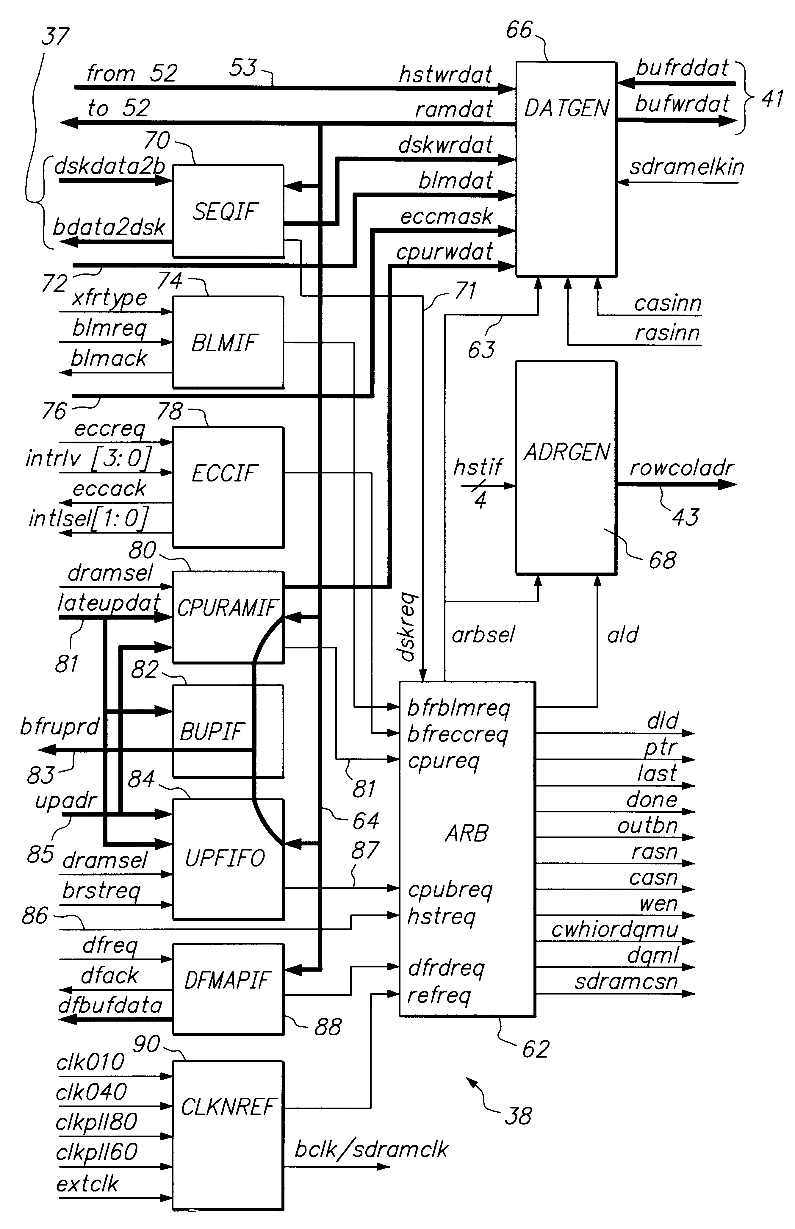
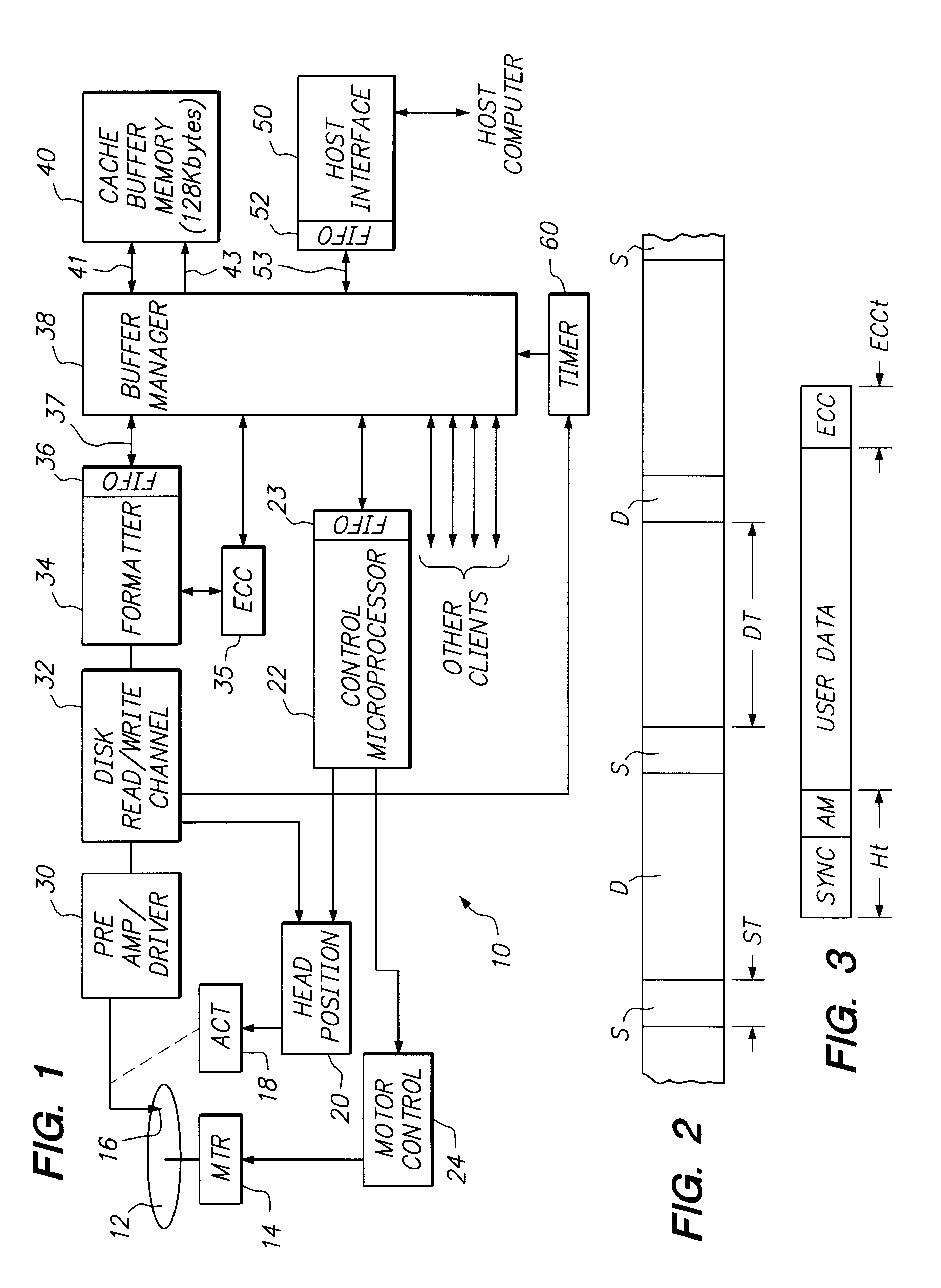
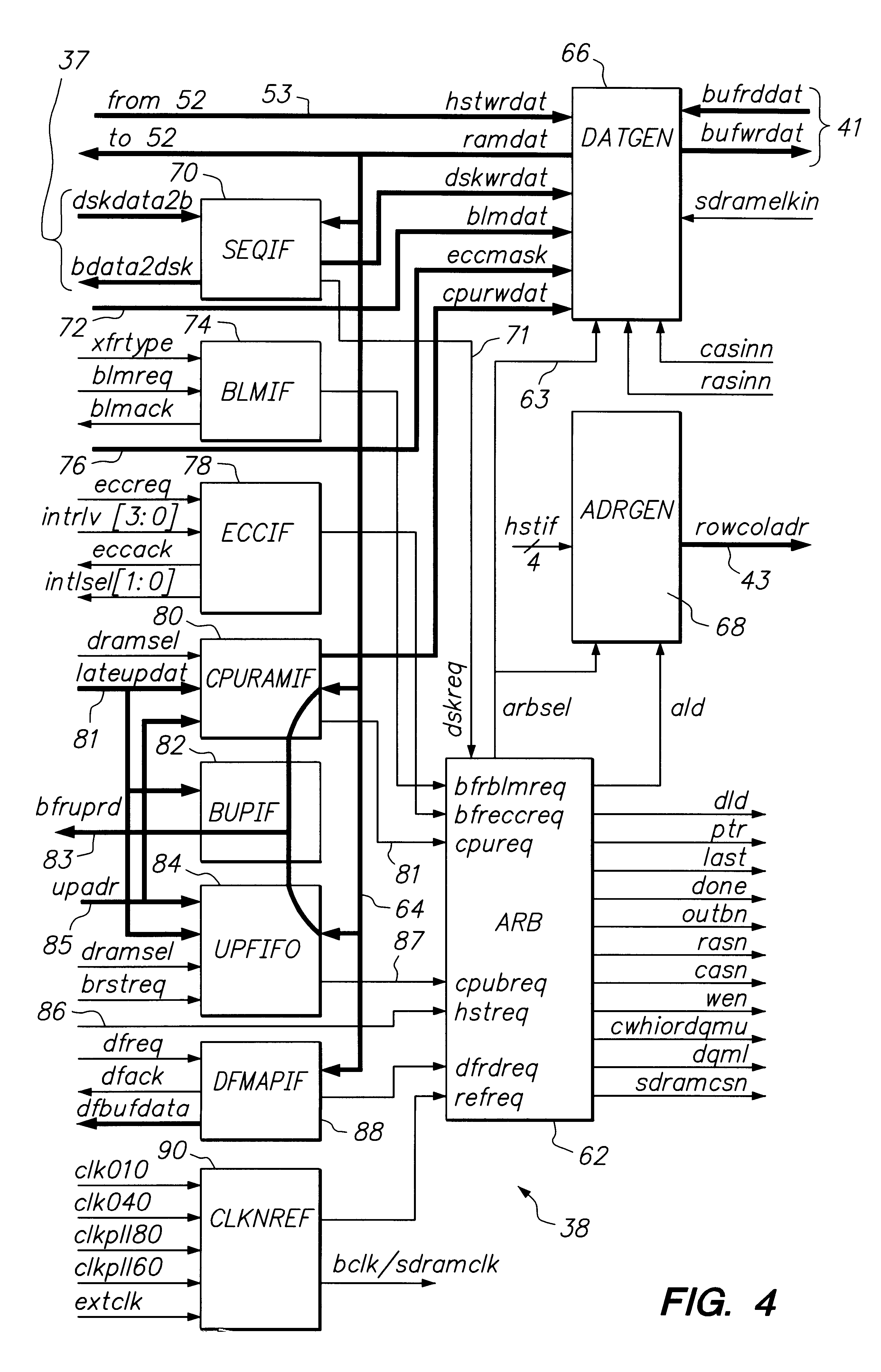
FIG. 1 sets forth a simplified block diagram of portions of a disk drive architecture which are pertinent to an understanding and appreciation of the present invention. An exemplary disk drive 10 includes a rotating data storage disk 12, and a spindle motor 14 for rotating the disk 12 at a predetermined rotational velocity. In the case of a Winchester or "flying head" disk drive, the velocity must be sufficient to sustain flying characteristics of a slider carrying a data transducer head 16; typically the rotational velocity will be in a range between 5000 RPM and 10000 RPM. An electromechanical actuator structure 18 is mechanically linked to the data transducer head 16 and functions to position the head 16 at each selected one of e.g. a multiplicity of concentric data tracks defined on the e.g. thin film magnetic recording surface of the data storage disk 12. The rotating disk 12, spindle motor 14, transducer 16 and actuator 18 are conventionally included within an enclosed, contam...


PUM


Abstract

A method and apparatus for arbitrating requests for access to a single buffer memory embedded within a disk drive in which a disk data channel is assigned a highest priority for buffer access within a queue. An arbitration cycle progressively services access requests pending within the queue, beginning with providing buffer access to the disk data channel and following with accesses to other channels during an arbitration cycle completion interval in accordance with a round-robin circular priority arrangement providing orderly access to all channels contending for memory access. At the end of completion interval, buffer access returns to the disk data channel, and thereafter, the arbitration cycle is repeated.

Description

FIELD OF THE INVENTIONThe present invention relates to buffer memory access management within a disk drive data storage device. More particularly, the present invention relates to improved priority and round-robin access arbitration to provide predictable bandwidth allocations and latencies for all buffer memory clients of a multiplexed memory system within a disk drive's embedded controller environment.BACKGROUND OF THE INVENTIONPrevious recent disk drive designs have included, in addition to a disk data channel and a host data channel, at least one embedded digital microprocessor for controlling various functions of the disk drive such as head positioning, spindle motor speed regulation, read channel adjustments for zoned data recording and error correction tasks, and the supervision of data block transfers between disk and host in response to host commands received via the host channel. These prior designs have typically included a large data cache memory array for temporary stor...

Claims


Application Information

Patent Timeline
Patent Type & Authority Patents(United States)
IPC IPC(8): G06F13/38G06F3/06G06F13/16
CPCG06F3/0613G06F3/0659G06F3/0674G06F13/1642G06F13/385
Inventor GILL, PARMINDERGOLD, CLIFFORD M.HENSON, JAMES A.
Owner MAXTOR
Learn More