Surface wave liquid sensor

a surface wave and liquid sensor technology, applied in the field of liquid sensor, can solve the problems of large disturbance of the measurement effect, high energy loss, and generation of compression waves, and achieve the effect of reducing disturbances, reducing disturbances, and increasing the measurement sensitivity to the viscosity of liquids

Inactive Publication Date: 2001-02-13
FRAUNHOFER GESELLSCHAFT ZUR FOERDERUNG DER ANGEWANDTEN FORSCHUNG EV
View PDF9 Cites 49 Cited by
  • Summary
  • Abstract
  • Description
  • Claims
  • Application Information

AI Technical Summary

Benefits of technology

To reduce the disturbances created by the so-called `triple transit echo`, the insertion loss of an electroacoustic wave between the transmitting transducer and the receiving transducer is set to a loss between 10 and 30 dB, preferably between 15 and 25 dB.
In the surface-wave sensor according to the present invention, interference between the surface shear wave, which constitutes the actual useful signal, and bulk shear waves, e.g. the `surface skimming bulk waves`, is prevented. By a suitable choice of the insertion loss, the influence of the so-called `triple transit echo` and an electromagnetic crosstalk between transmitting transducer and receiving transducer can also be reduced considerably. At the same time, the sensor according to the present invention provides increased measurement sensitivity to the viscosity of liquids. Disturbances in the measurement effect are thereby greatly reduced.

Problems solved by technology

If surface-wave components are to be used as sensors for the measurement of physical liquid properties, e.g. the density, the viscosity, the shear rigidity, the conductivity, the dielectric constant, etc., Rayleigh-wave modes lead to the generation of compression waves and thus to a high energy loss.
When surface-shear-wave components of this type are used as sensors for the measurement of liquid properties, problems arise that play no part or only a minor part when they are used as filters.
The gravest of these problems arises from the simultaneous excitation of surface shear waves (SSWs) and bulk shear waves (SSBWs) and the interference of these waves.
Another problem, that can lead to considerable disturbances in the measurement effect, is the so-called `triple transit echo`.
These effects, which will be explained in more detail in the subsequent description of the present patent application, give rise to problems which render these known components unsuitable for liquid sensor applications.

Method used


Image

  • Surface wave liquid sensor
  • Surface wave liquid sensor
  • Surface wave liquid sensor

Examples


Embodiment Construction

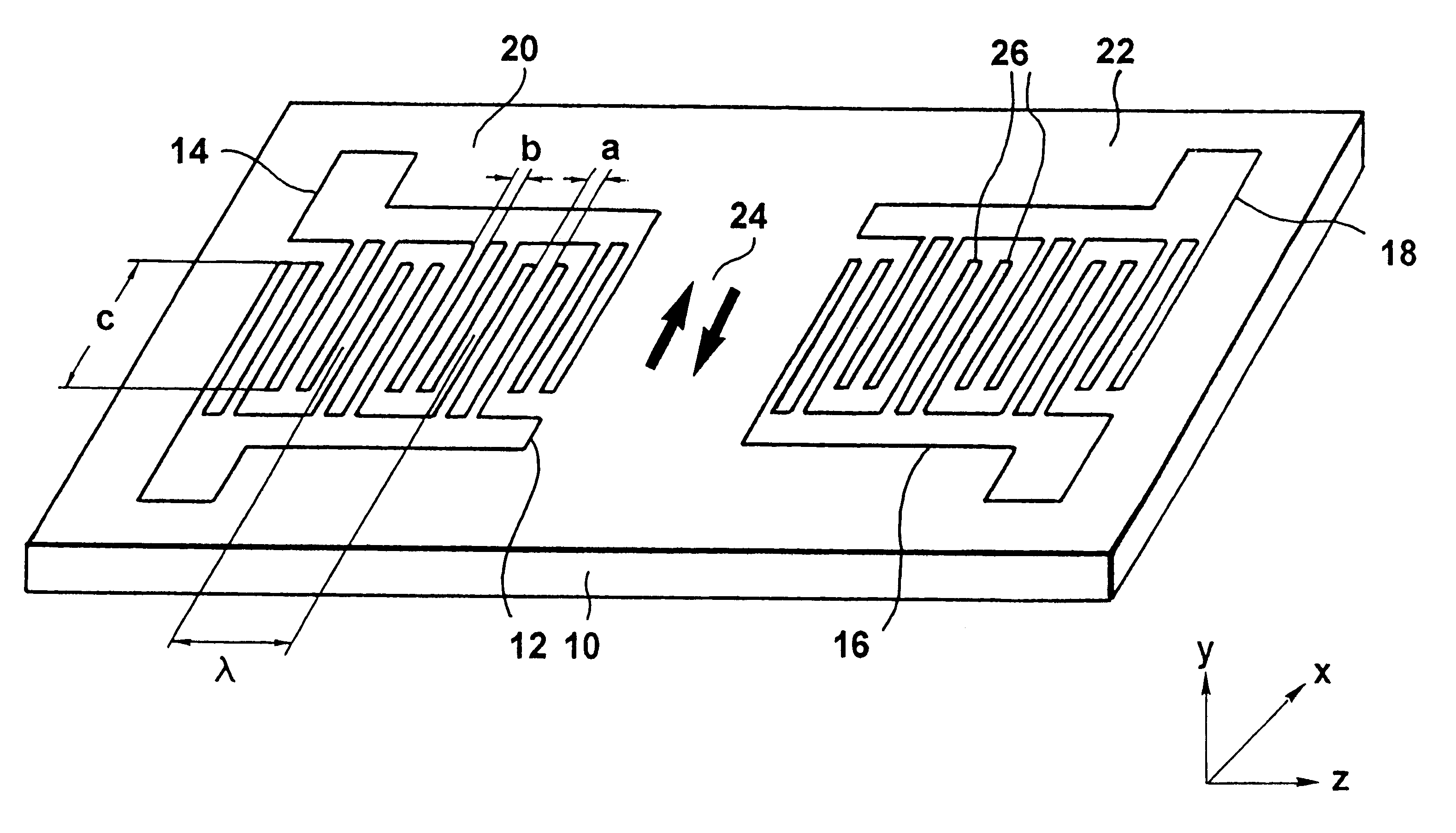
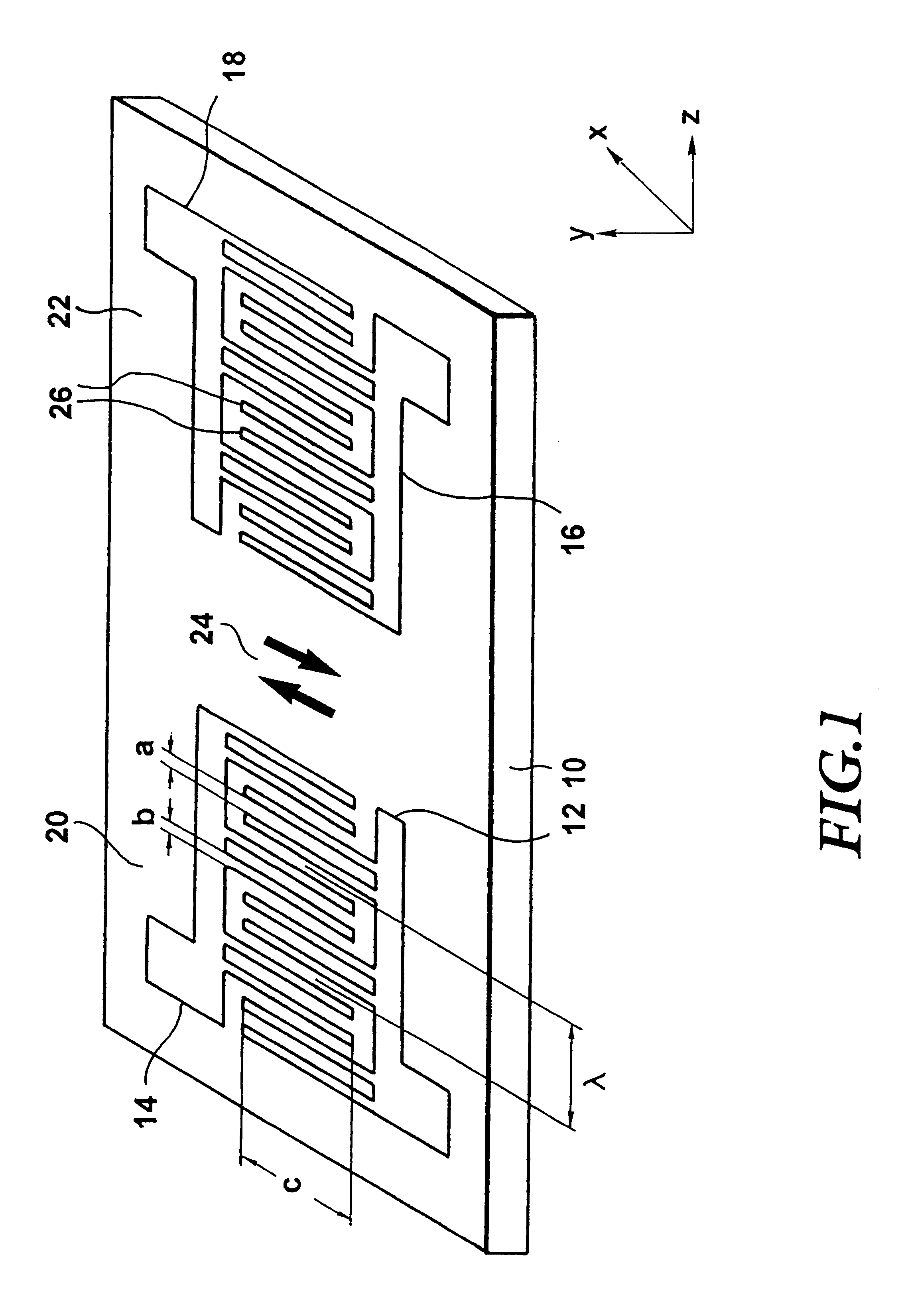
In the following a general description of the surface-wave component shown in FIG. 1 will be given in brief. A piezoelectric substrate 10, e.g. a y-rotated quartz crystal, has comb-shaped electrodes 12, 14, 16 and 18, in thin-film technology e.g., applied to it. The electrodes 12 and 14 form a first interdigital transducer (IDT) 20, the so-called transmitting interdigital transducer (transmitting IDT), while the electrodes 16 and 18 form a second interdigital transducer 22, the so-called receiving interdigital transducer (receiving IDT). The substrate can consist of any sort of piezoelectric material which is suitable for the excitation of shear waves. Preferably a y-rotated quartz crystal with a quartz crystal cut between 35.degree. and 40.degree. is used.

When a high-frequency alternating voltage is applied to the transmitting IDT 20, electroacoustic waves, represented schematically in FIG. 1 by the arrows with the reference numeral 24, are generated because of the piezoelectricity...


PUM

PropertyMeasurementUnit
excitation frequencyaaaaaaaaaa
insertion lossaaaaaaaaaa

Abstract

A liquid sensor has comb-shaped electrodes, applied to a piezoelectric substrate, as interdigital transducers for generating an electroacoustic wave from a transmitting transducer to a receiving transducer. The number of finger pairs of the interdigital transducers and the material out of which the electrodes are made are so chosen that a surface shear wave generated by the transmitting transducer and a bulk shear wave generated by the transmitting transducer have different frequencies.

Description

1. Field of the InventionThe present invention relates to a liquid sensor and in particular to a liquid sensor which is composed of a surface-wave component.2. Description of Prior ArtSurface-wave components have been used for decades in electronics, e.g. as bandpass filters for the high-frequency region, and manufactured in large quantities. Depending on the choice of material used for the substrate, different wave-forms are excited. For example, for gas sensor applications, Rayleigh-wave components with a deflection perpendicular to the surface are normally used. Such components, provided with a selective layer, are employed as bio / chemosensors.If surface-wave components are to be used as sensors for the measurement of physical liquid properties, e.g. the density, the viscosity, the shear rigidity, the conductivity, the dielectric constant, etc., Rayleigh-wave modes lead to the generation of compression waves and thus to a high energy loss. For liquid sensors, components which gen...

Claims


Application Information

Patent Timeline
Patent Type & Authority Patents(United States)
IPC IPC(8): G01N29/02H03H9/02H03H9/145
CPCG01N29/022H03H9/02866H03H9/14552G01N2291/02818G01N2291/0422G01N2291/0423G01N2291/0426
Inventor LEIDL, ANTON
Owner FRAUNHOFER GESELLSCHAFT ZUR FOERDERUNG DER ANGEWANDTEN FORSCHUNG EV
Why Eureka
Try Eureka