Captivity point detection system with single switch position target

Inactive Publication Date: 2001-02-13
ANSALDO STS USA INC
View PDF7 Cites 32 Cited by
  • Summary
  • Abstract
  • Description
  • Claims
  • Application Information

AI Technical Summary

Problems solved by technology

A common problem in the related art electro-mechanical type point detection and indication systems is slack or lost motion in the mechanism that results due to wear over time.
Over time, the mechanical linkages wear, thereby creating slack or lost motion in the mechanism.
With undesired slack or lost motion, if the point detector bar should move unintentionally, thereby indicating unsafe switch point movement, the mechanical linkages detecting the internal point detector bar must move a given distance to take up or absorb the lost motion before the mechanical contacts or similar devices are actuated.
The result is decreased sensitivity in switch point monitoring, which ultimately may cause an undesirable safety hazard.
Another problem with related art point detection and indication systems is that their design commonly requires the point detector bar to protrude out both sides of the switch mach

Method used


Image

  • Captivity point detection system with single switch position target
  • Captivity point detection system with single switch position target
  • Captivity point detection system with single switch position target

Examples


Embodiment Construction

of the Figures

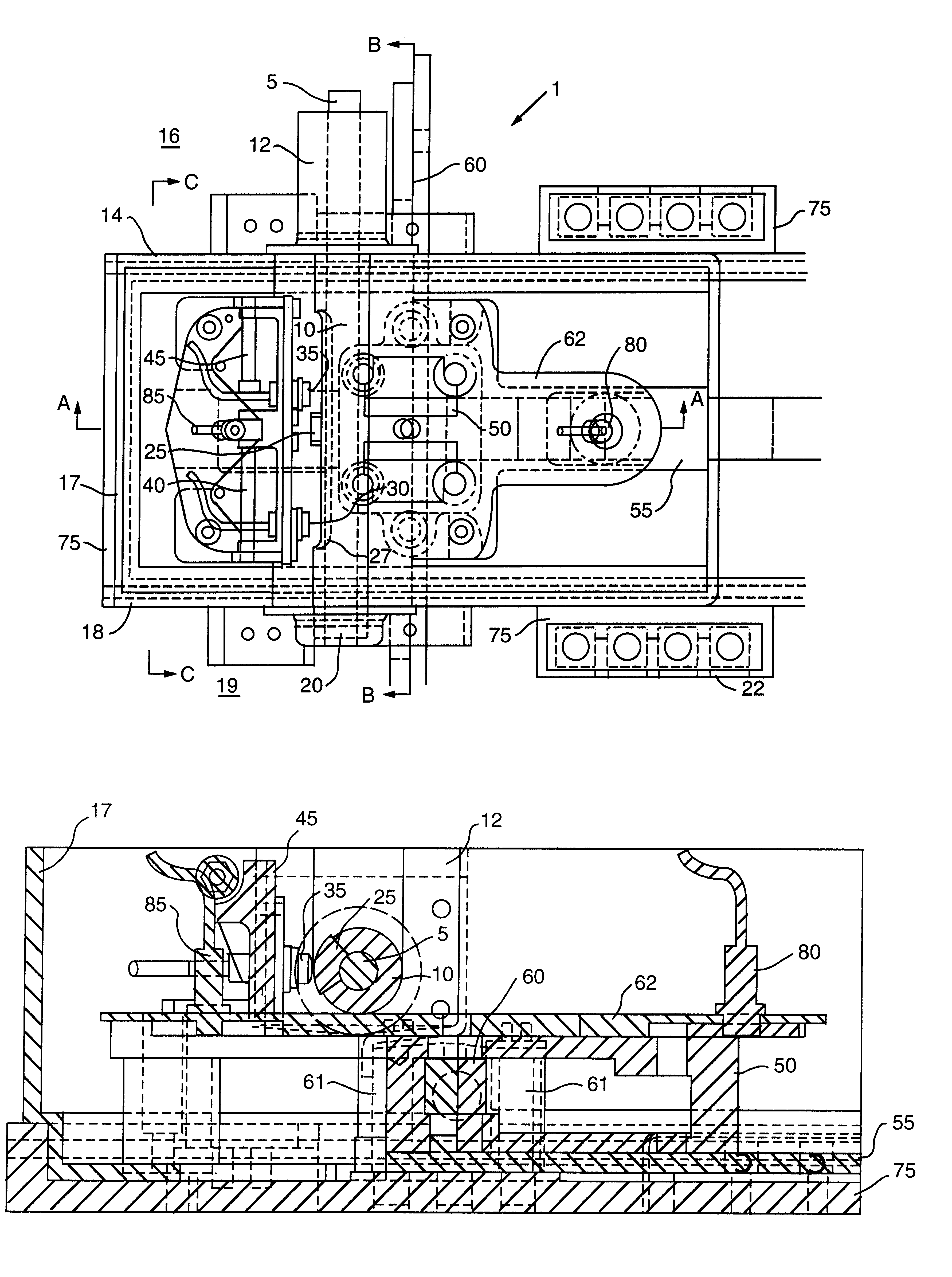
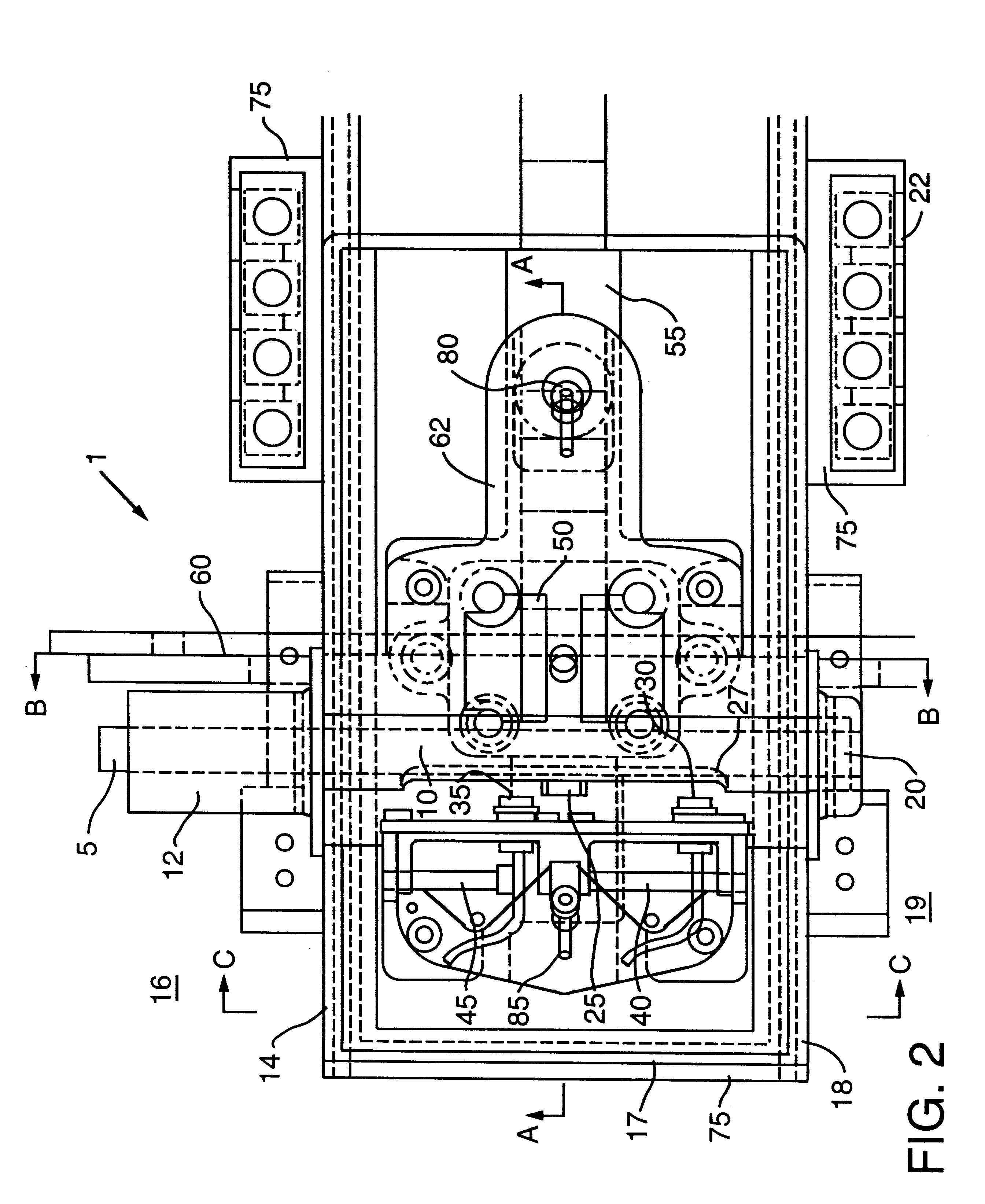
Referring to FIGS. 2 through 5 and, in particular, FIG. 2, a top planar view of a point detection system 1 is shown in accordance with a preferred embodiment of the present invention. A point detector bar 5 (shown partially in phantom in FIG. 2) may be held slidably captive within a point detector sleeve 10 and within a track side bearing 12 mounted to a wall 14 on a track side 16 of a controller housing 17, thereby to support the point detector sleeve 10 and the point detector bar 5. In a preferred embodiment, the point detector sleeve 10 may extend the internal width of the controller housing 17 between the wall 14 and a wall 18 on a field side 19 of the controller housing 17, as shown in FIG. 2. A field side bearing 20 may be mounted to the wall 18 and may support the point detector sleeve 10. A point detector target 25 may be affixed to the point detector bar 5 and may be exposed to be detected or sensed through a slot 27 defined in the captive point detector sleev...


PUM


Abstract

A point detection system is provided for use in a typical switch machine with a typical indication system, wherein a point detector bar is slidably captivated within a point detector sleeve, and wherein a target that is integrally engaged with the point detector bar is sensed by at least one sensing device, thereby to detect movement of the point detector bar. The point detector sleeve is supported by a track side bearing affixed to a track side wall of the switch machine, and by a field side bearing affixed to an opposing wall of the switch machine. The point detector bar extends outside the switch machine from only the track side bearing, thereby eliminating the bearings and the pinch point between the hand throw lever and the two piece point detector bar that otherwise extended from the related art switch machine. The sensing device may be mounted upon a slide mechanism to adjust the sensing device relative to the target. Use of the sensing device eliminates the need for cams to monitor in order to detect movement of the point detector bar, as well as eliminates moving parts between the cams and the mechanical linkages. Further, at least one other sensing device detects a normal and reverse locked position of a lock bar assembly and lock box of the switch machine.

Description

1. Field of the InventionThe present invention relates generally to an electric motor driven switch machine for switching railroad tracks so that trains may switch from one track to another. More particularly, the present invention relates to a captive point detection system of a switch machine, for detecting, with a single switch position target, whether a railroad track has been properly switched, in order that such detection may indicated by indication means positioned locally at the switch machine or at a remote location.2. Description of the Related ArtAs is known in the art, a common method for switching a train from one railroad track to another is to install an electric motor driven switch machine next to a switching point of the track. Since modern versions of these switch machines are usually operated from a remote location, it is essential that a remote operator be able to determine that the switch has, in fact, been thrown as requested. Moreover, because switch point clo...

Claims


Application Information

Patent Timeline
IPC IPC(8): B61L5/00B61L5/10
CPCB61L5/107B61L5/00
Inventor WYDOTIS, LEONARD M.BRUSHWOOD, DANIEL H.
Owner ANSALDO STS USA INC
Why Eureka
Try Eureka