Diffraction grating with electrically controlled periodicity

a diffraction grating and periodicity technology, applied in the field of diffraction gratings, can solve the problem of limiting the ability to modify the diffraction of light beams

Inactive Publication Date: 2001-02-13
KENT STATE UNIV
View PDF3 Cites 126 Cited by
  • Summary
  • Abstract
  • Description
  • Claims
  • Application Information

AI Technical Summary

Problems solved by technology

These gratings have a fixed grating period which lim...

Method used


Image

  • Diffraction grating with electrically controlled periodicity
  • Diffraction grating with electrically controlled periodicity

Examples


example 1

A cholesteric material was obtained by doping a nematic liquid crystal, E7 from EM industries, Inc., having positive dielectric anisotropy .DELTA..di-elect cons.=13.8 at voltage frequency f=1 kHz, refractive indices n.sub.0 =1.522, n.sub.e =1.746 at 20.degree. C., with a chiral agent, CB15 from EM Industries, Inc. The chiral mixture was disposed between two glass plates with ITO electrodes. The electrodes were coated with a polyimide, SE-610 from Nissan Chem., Inc., and were rubbed unidirectional to provide an in-plane easy axis of molecular orientation. The unidirectionally rubbing caused surface anchoring of the cholesteric material that provided for uniformity of modulations in the plane of the cell with the modulations caused by an applied electrical field.

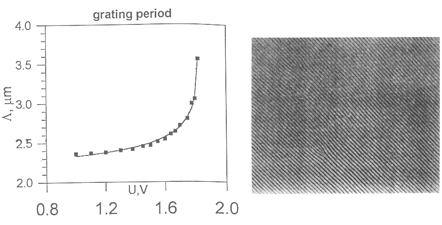
Described herein are two cells with different weight concentration, c, of the chiral additive thus giving different equilibrium pitch, p, of the cholesteric bulk. Cell number 1: c=17%, p=0.7 .mu.m, cell thickness (measured by ...

example 2

A liquid crystal cell was prepared. Walls of the cell were coated with polyimide (SE-610 supplied by Nissan Chem. Ind.) to provide a slightly tilted, 5.degree.-10.degree. with respect to the wall, director orientation. The polyimide layers were rubbed unidirectional to define an in-plane component of easy axis of the molecular orientation. Two types of cells were prepared a) .gamma.=90.degree. and 270.degree. director twist; and b) with .gamma.=0.degree. and 360.degree. director twist. The cells were filled with nematic liquid crystal LX ZLI 5200-000, supplied by E. Merck, having positive dielectric anisotropy .DELTA..di-elect cons. of about 5.9 and refractive indices n.sub.o of about 1.494, for ordinary waves, and n.sub.e of about 1.614, for extraordinary waves, at 20.degree. C. The nematic liquid crystal was doped with chiral agent CB 15, supplied by EM Industries. The cells were vacuum filled, and the thickness of the cell, d, is about 5-6 .mu.m. To obtain an optimal grating patt...


PUM


Abstract

The present invention is directed to liquid crystal diffraction gratings with electrically controlled periodicity. An electrical field is applied to liquid crystal device wherein the liquid crystals align to form a diffraction grating. The period of the diffraction grating is varied by changing the applied electrical field. The diffraction grating therefore has a period that can be varied by an electrical field.

Description

FIELD OF THE INVENTIONThe present invention is directed to diffraction gratings. More particularly, the present invention is directed to a liquid crystal diffraction grating with electrically controlled periodicity.BACKGROUND OF THE INVENTIONA diffraction grating is a series of parallel fine lines, slits or grooves on a substrate that diffract light passing through the grating. The grating period is the number of lines per unit length.Presently, diffraction gratings are mainly constructed from mechanical means. These gratings have a fixed grating period which limits the ability to modify the diffraction of a light beam.It is possible for liquid crystals to diffract light. Diffraction occurs whenever the orientation of liquid crystal molecules, described by the liquid crystal director, is periodically modulated in space. Spatial modulation of the director implies spatial modulation of the effective refractive index so that the liquid crystal serves as the phase diffraction grating. C...

Claims


Application Information

Patent Timeline
IPC IPC(8): G02F1/13G02F1/137
CPCG02F1/13718G02F2201/305
Inventor LAVRENTOVICH, OLEG D.SUBACIUS, DARIUS
Owner KENT STATE UNIV
Why Eureka
Try Eureka