
Method of making a double-walled flexible tubing product with helical support bead and heating conductor

Inactive Publication Date: 2001-02-20
STEWARD PLASTICS INC
View PDF29 Cites 93 Cited by
  • Summary
  • Abstract
  • Description
  • Claims
  • Application Information

AI Technical Summary

Benefits of technology

It would be an advantage if a flexible, support-bead, double-walled, smooth-bore tubing product having a high insulation value between warmed tidal air and ambient, as well as an electrical resistance heating conductor extending helically along the length of the tube for offsetting heat loss to ambient from warmed tidal air flow in the tube were available. Such a tubing product would provide a combination of the desirably low heat loss to ambient from tidal air flow in the tubing product which conventional double-walled tubing provides, and also would provide the desirably low or zero temperature loss from tidal air flow like the Carlson '061 tubing, because of the electrical resistance heating available from the heating conductor.
To this end, it is an object for this invention to provide a tubing product which provides a flexible, lightweight, crush-resistant double-walled tubing having a pair of radially spaced apart walls confining an insulative dead-air space therebetween, and an electrical heating conductor in the form of a wire helically imbedded in the tubing. A helical support bead is helically wound about the inner one of the two walls and over the heating wire. The outer wall is formed atop the helical support bead and spans from wrap to wrap of this support bead. All of the inner wall, outer wall, and support bead are integral with one another by mutual heat bonding.
It is another object of this invention to provide apparatus and method for inexpensively making a flexible, double-walled, heatable tubing including resistance wire, supporting bead, and tube walls as a unitary body free of adhesive and binders and having both inner and outer surfaces which are substantially smooth.
While other melt-extrudable, heat-bondable plastics may be successfully used in the making of tubing product according to this invention, a preferred material is a polyolefin plastomer (i.e., a plastic and elastic polymer) product. This material may be an ethylene alpha-olefin resin primarily intended for blown-film applications in the packaging industry. However, experience with material of this type in making tubing product according to the present disclosure has yielded excellent results, and its optical qualities are such that the tubing product has desirable transparency, clarity, and freedom from yellowing, milkiness, and opacity.

Problems solved by technology

Conventional unheated tubing allows significant heat loss to ambient and cooling of the warmed inhalation air, to the detriment of critical or tenuous patients. cooling of the conditioned air may cause considerable condensation of added humidity within the conventional tubing.
For example, tubing which relies on an adhesive binding for the support bead may deteriorate as a result of repeated sterilization.
Materials may be biomedically incompatible, and exteriors are invariably characterized by crevices adjacent to the support bead which can harbor particulate matter and microbes.
In addition, the more separate and distinct steps that are required in producing such tubing, the greater the cost, complexity and potential for failure of the product in use.
Also, the separate glue may not provide as secure an attachment of the heating conductors to the respiratory tube as would be desired.
There is a distinct possibility of imperfect match between the tube and the glue, and the glue also presents a possibility of solvents being released in the medical environment.
As previously mentioned, the glue may not endure sterilization as well as the tube itself.
Even though this conventional double-walled tubing is an improvement in some uses over the conventional un-heated single-walled support-bead tubing, it does not entirely eliminate heat loss to ambient from warmed tidal air flow in the tubing.
In this respect, the conventional double-walled support-bead tubing cannot provide essentially a zero heat loss from tidal air flow along a length of the tubing, as can the electrically heated tubing of Carlson, disclosed in his '061 patent.
No prior product, method of manufacture, or apparatus is known which provides a flexible, support-bead, double-walled, smooth-bore tube having a high insulation value between warmed tidal air and ambient, as well as an electrical resistance heating conductor extending helically along the length of the tube for offsetting heat loss to ambient from warmed tidal air flow in the tube.

Method used


Image

  • Method of making a double-walled flexible tubing product with helical support bead and heating conductor
  • Method of making a double-walled flexible tubing product with helical support bead and heating conductor
  • Method of making a double-walled flexible tubing product with helical support bead and heating conductor

Examples


Embodiment Construction

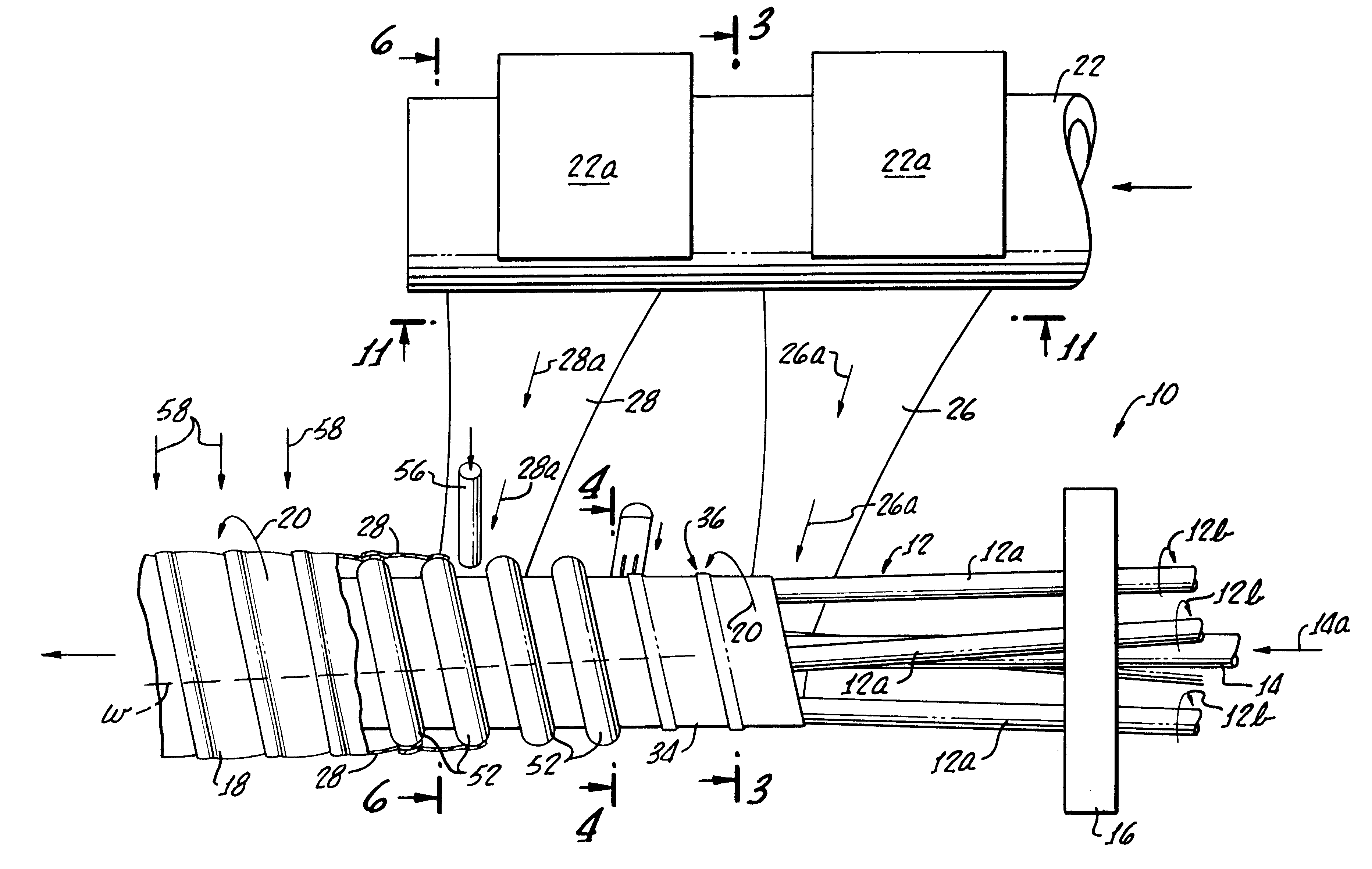
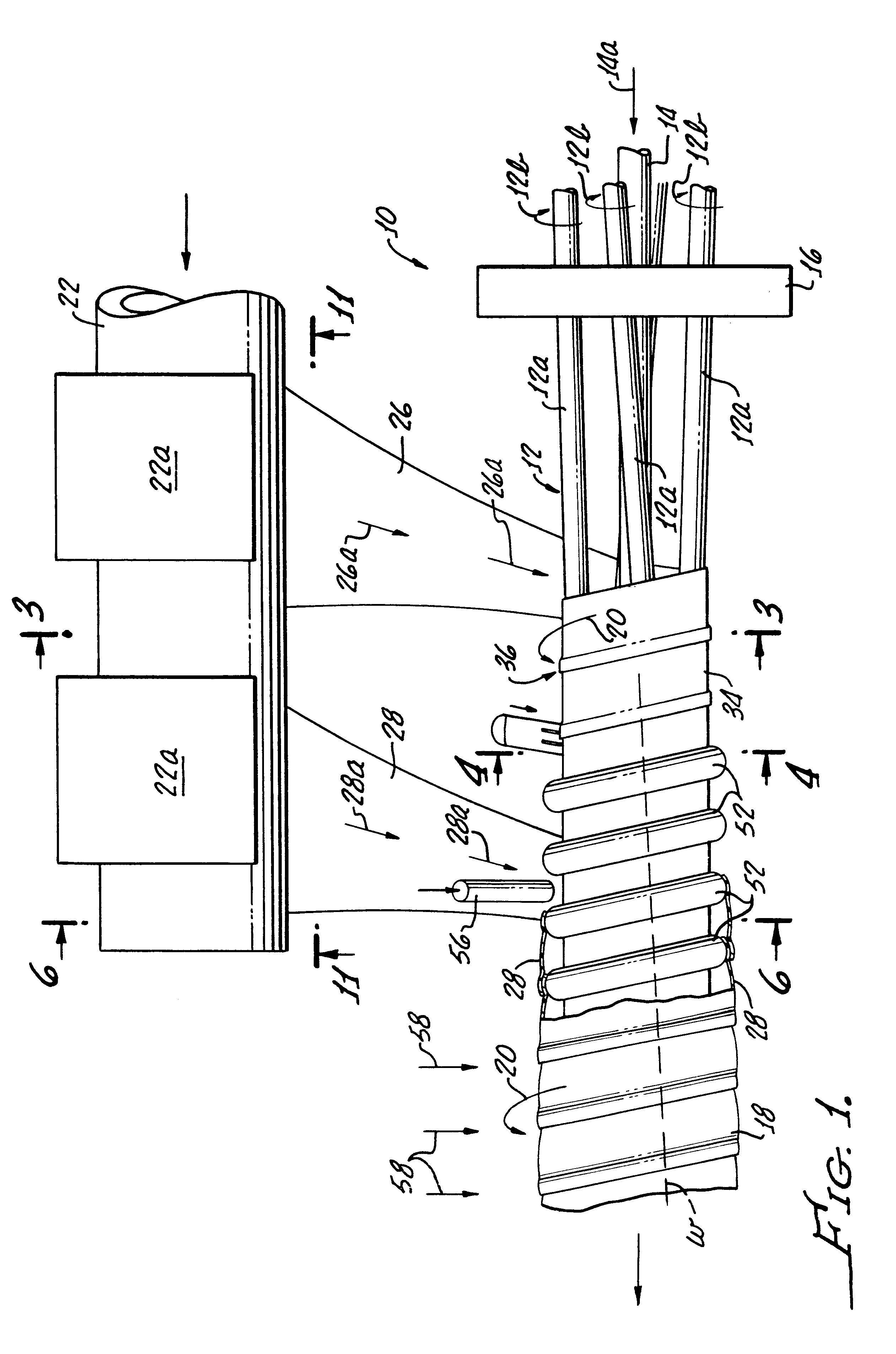
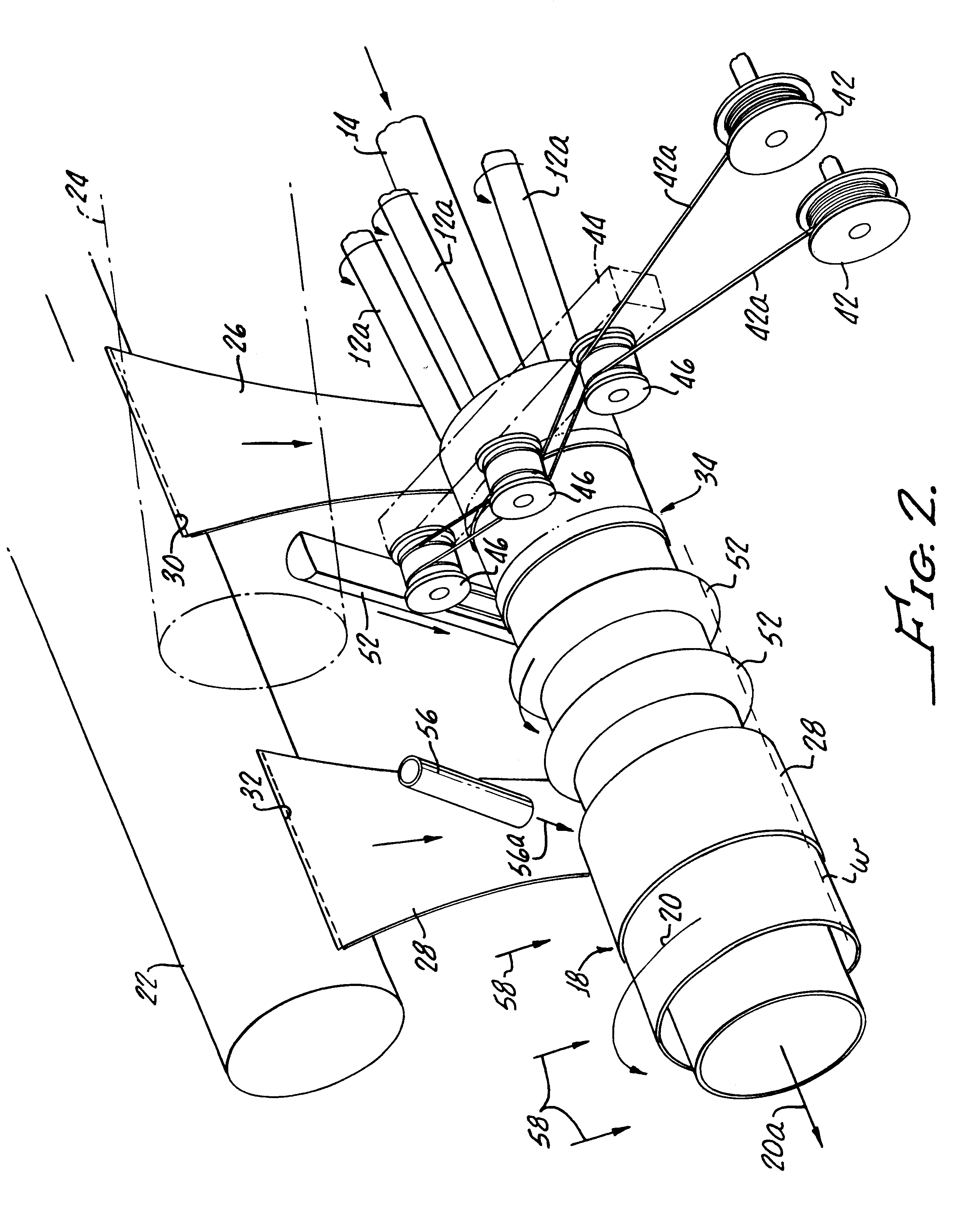
The manufacturing apparatus and method of making a tubing product embodying the present invention, as well as the tubing product itself, are illustrated in the appended drawing figures. FIG. 1 illustrates the manufacturing apparatus 10 including a compound winding mandrel 12 made up of plural power-driven winding rollers 12a. The winding rollers 12a in this case are four in number and are arrayed at 90.degree. to one another around a cooling water tube 14 in a bearing plate 16. All of the winding rollers 12a rotate in synchronization in a clockwise direction when viewed from the right end of FIG. 1, noting the rotation arrows 12b. In this case, the bearing plate 16 of compound mandrel 12 includes spherical bearing inserts (not shown).

The spherical bearing inserts of the plate 16 allow this plate to be positioned with a slight relative rotation with respect to the location of corresponding individual drive shafts from a common gear box (not shown) which provides the driving power for...


PUM

PropertyMeasurementUnit
Electrical resistanceaaaaaaaaaa
Flexibilityaaaaaaaaaa
Thermoplasticityaaaaaaaaaa

Abstract

A flexible double-walled plastic tubing product includes a helically wound support bead between inner and outer walls, and an helically wrapped electrical resistance heating conductor is disposed adjacent to the inner wall in good heat transfer relation to fluid flow within the tubing product. Fluid flow within the tubing product is insulated against heat loss to ambient by the helical support bead and a trapped "dead-air" space between the walls of the tubing product. Apparatus and method for making the tubing product are disclosed.

Description

1. Field of the InventionThe present invention relates in general to flexible plastic tubing and, more particularly, to apparatus and methods for making double-walled flexible plastic tubing having a helical support bead and integrally incorporating at least one electrical resistance heating conductor. Still more particularly, the present invention relates to a flexible double-walled and electrically-heated plastic tubing having a greatly reduced rate of heat loss compared to conventional single-walled tubing of this type. The present tubing further is configured to maintain a substantially smooth bore even when bent.2. Description of Related ArtThroughout this disclosure, it will be recalled that heat transfer in a body, or between the interior of a body and ambient (i.e., heat loss from within a body to ambient) may be considered either from the standpoint of heat transfer conductivity (C) (a measure of heat transfer quantity per unit of area per degree of temperature difference),...

Claims


Application Information

Patent Timeline
IPC IPC(8): B29C53/82B29C53/58B29C53/00F16L11/24F16L11/12F16L11/127F16L11/00F24H1/12F24H1/14H05B3/42H05B3/40A61M16/10A61M16/08B29C35/00B29C35/16B29C47/00B29C48/00B29C48/07B29C48/12
CPCB29C47/0019B29C47/003B29C53/582B29C53/583B29C53/827F16L11/127F16L11/24F24H1/142H05B3/40H05B3/42A61M16/1095A61M16/08B29C47/00B29C2035/1616B29K2995/0026B29L2031/753H05B2203/022A61M16/0875B29C48/00B29C48/07B29C48/12
Inventor CARLSON, LENNART L.
Owner STEWARD PLASTICS INC
Learn More