Selective deposition modeling method and apparatus for forming three-dimensional objects and supports

a three-dimensional object and selective deposition technology, applied in additive manufacturing processes, manufacturing tools, coatings, etc., can solve the problems of unsatisfactory support function, unsolidified material is not available to perform the support function, and nothing is available to provide a working surface for or to suppor

Inactive Publication Date: 2001-02-27
3D SYST INC
View PDF25 Cites 473 Cited by
  • Summary
  • Abstract
  • Description
  • Claims
  • Application Information

AI Technical Summary

Benefits of technology

An eleventh object of the invention is to provide a method and apparatus that forms a support structure that is easily removed from up-facing surfaces of the object.
A twel

Problems solved by technology

As these factors cannot typically be optimized simultaneously, a selection of an appropriate building technique and associated method and apparatus involve trade offs depending on specific needs and circumstances.
However, since the third approach, SDM, does not necessarily supply a working surface, it suffers from a particularly acute problem of accurately forming and placing subsequent lamina which contain regions not fully supported by previously dispensed material such as regions including outward facing surfaces of the object in the direction of the previously dispensed material.
In the typical building process where subsequent laminae are placed above previously formed laminae this is particularly a problem for down-facing surfaces (down-facing portions of laminae) of the object.
Thus, nothing will be available to provide a working surface for or to support any down-facing surfaces appearing on a subsequent cross-section.
ly. The previous lamina is non-existent in down-facing regions and is thus unavailable to perform the desired support funct
ion. Similarly, unsolidified material is not available to perform the support function since, by definition, in the third approach, such material is typically not deposited in areas which do not become part of an object cross-sect
ion. The problem resulting from this situation may be referred to as the "lack of working surface" pro
Thus, with the SDM approach, there is nothing to provide a working surface for or to support the two down-facing surfaces.
Several mechanisms have been proposed to address this problem, but heretofore, none has proven completely satisfactory.
A problem with the two material (i.e. building material and different support material) approach is that it is expensive and cumbersome because of the inefficiencies, heat dissipation requirements, and costs associated with handling and delivering the support, or second, material.
A multitude of problems have occurred with this approach.
A first problem has involved the inability to make sup

Method used


Image

  • Selective deposition modeling method and apparatus for forming three-dimensional objects and supports
  • Selective deposition modeling method and apparatus for forming three-dimensional objects and supports
  • Selective deposition modeling method and apparatus for forming three-dimensional objects and supports

Examples


second embodiment

A second embodiment involves the following preferred steps: 1) forming a layer; 2) optically detecting a misfiring jet; 3) rescanning the lines on the layer that should have been formed by the misfiring jet; 4) ceasing the use of the misfiring jet in the remainder of the building process; and 5) scanning subsequent layers while compensating for the misfiring jet (i.e., make extra passes with a working jet to cover the lines corresponding to the misfiring jet). Optionally, the misfiring jet may be periodically checked to see if it has started functioning again. If so, this jet is put back into operation. Another option involves putting a misfiring jet through a reactivation routine to see if it can be made operational. This could occur during the building process or during servicing of the system. As a further alternative, it may be possible to determine whether or not a jet is firing correctly by tracking the electrical characteristics of the piezo electric element as firing is to o...

third embodiment

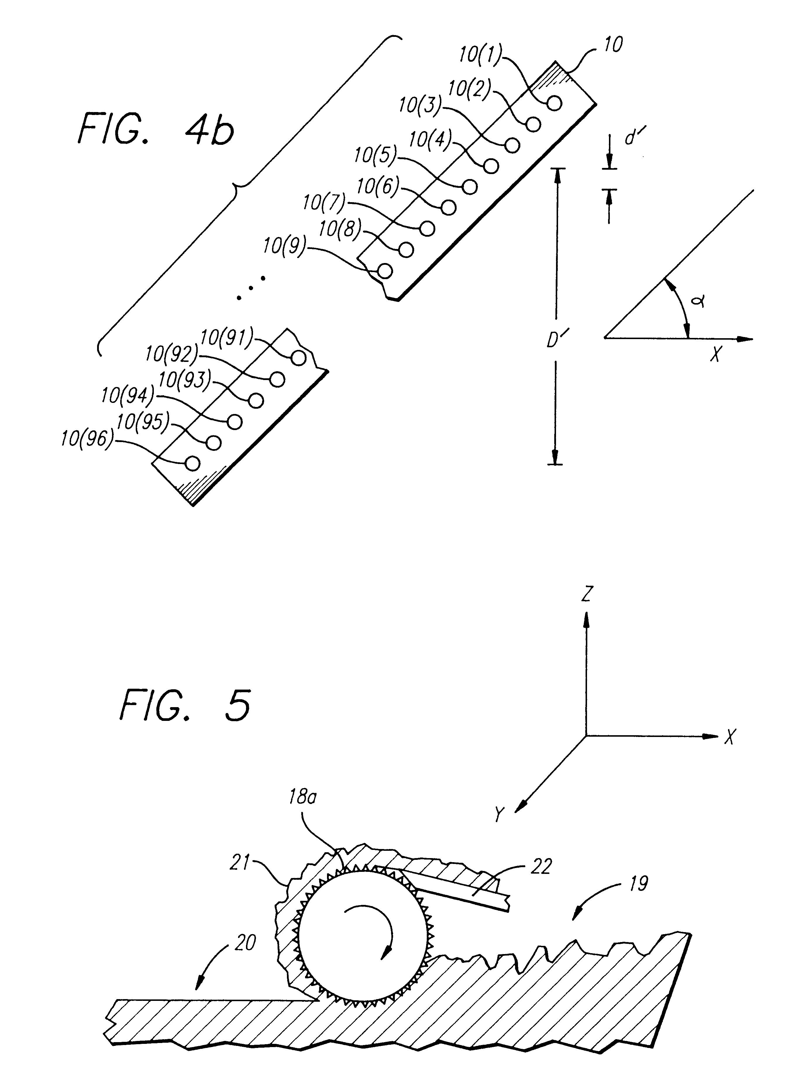
A third embodiment might involve the use of a flexible element for wiping excess material from the bottom of the print head. This embodiment involves the firing of all the jets followed by a wiping of the orifice plate with a heated rubber (e.g. VITON) blade. Preferably the blade is positioned such that it contacts the orifice plate as they are relatively moved passed each other thereby causing a squeegee action to remove excess material from the orifice plate and hopefully revitalizing any jets which were not behaving properly. It is further preferred that the orifice plate and blade be positioned at an angle to each other such that at any one time during their contact only a portion of the orifice plate is in contact with the squeegee thereby minimizing the force the blade exerts on the orifice plate.

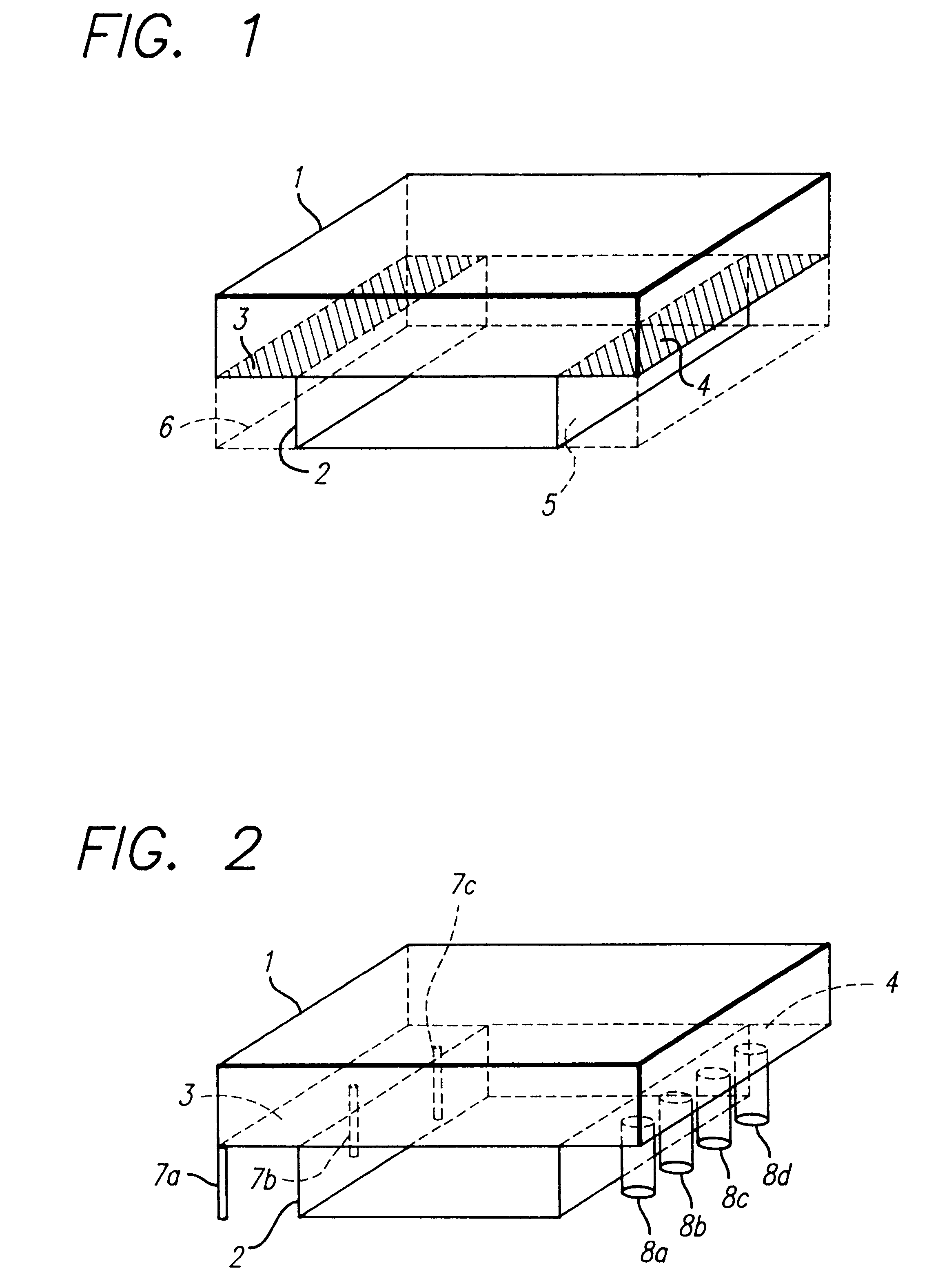
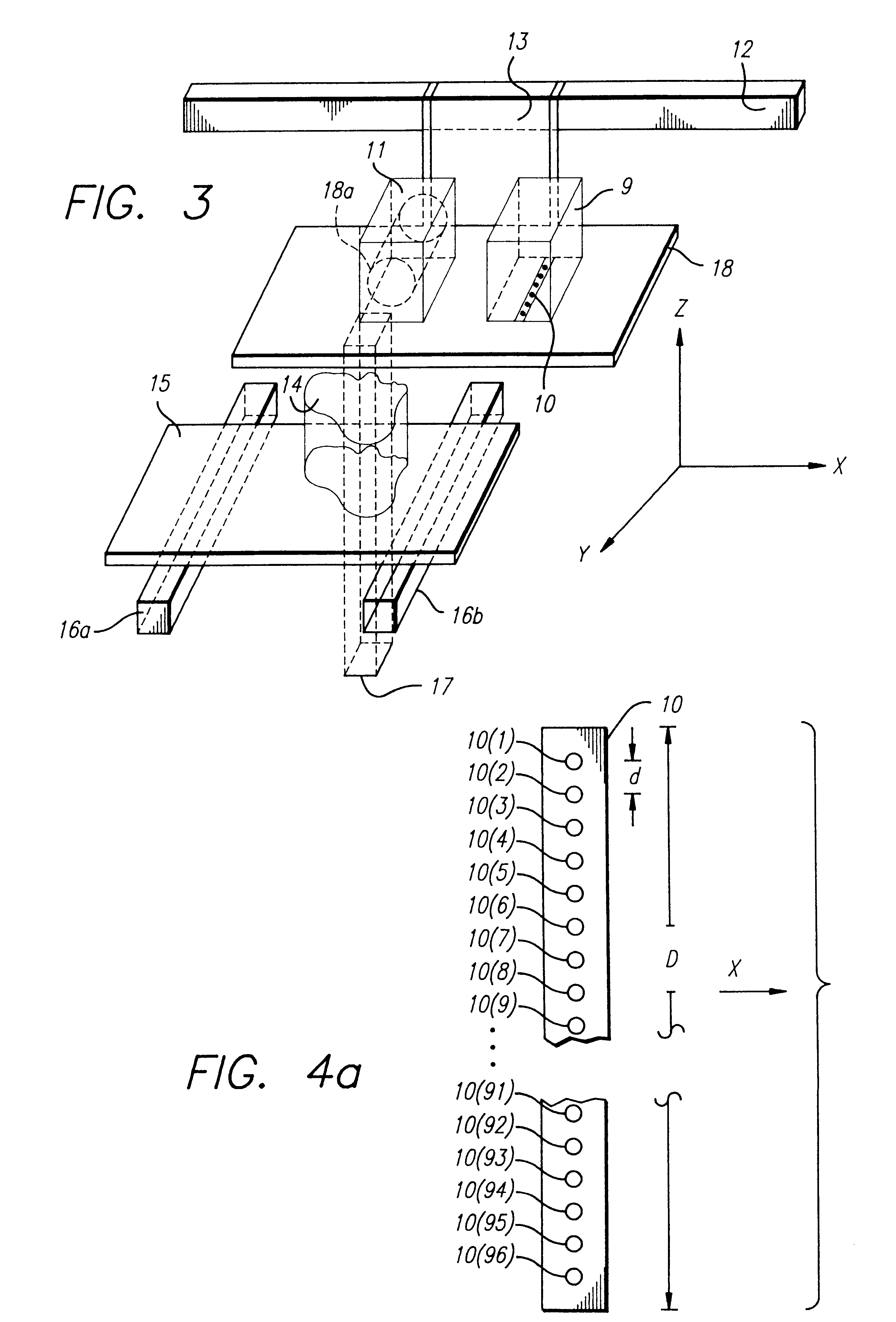
The orifice plate 10 is mounted on the dispensing platform 18 such that droplets of material are allowed to emit from the underside of the dispensing platform 18. The orifice plate 10...


PUM

PropertyMeasurementUnit
Thicknessaaaaaaaaaa
Flow rateaaaaaaaaaa
Areaaaaaaaaaaa

Abstract

A variety of support structures and build styles for use in Rapid Prototyping and Manufacturing systems are described wherein particular emphasis is given to Thermal Stereolithography, Fused Deposition Modeling, and Selective Deposition Modeling systems, and wherein a 3D modeling system is presented which uses multijet dispensing and a single material for both object and support formation.

Description

This invention relates to techniques for forming three-dimensional (3D) objects and supporting those objects during formation; more particularly, it relates to techniques for use in Rapid Prototyping and Manufacturing (RP&M) Systems; and most particularly to building and supporting methods and apparatus for use in a Thermal Stereolithography (TSL) system, Fused Deposition Modeling (FDM) system, or other Selective Deposition Modeling (SDM) system.BACKGROUND INFORMATIONVarious approaches to automated or semi-automated three-dimensional object production or Rapid Prototyping & Manufacturing have become available in recent years, characterized in that each proceeds by building up 3D objects from 3D computer data descriptive of the objects in an additive manner from a plurality of formed and adhered laminae. These laminae are sometimes called object cross-sections, layers of structure, object layers, layers of the object, or simply layers (if the context makes it clear that solidified st...

Claims


Application Information

Patent Timeline
IPC IPC(8): B29C41/12B29C41/34B29C41/36B29C67/00
CPCB29C41/12B29C41/36B29C67/0055B29C67/0059B29C67/0092B29C64/112B29C64/40B33Y30/00B33Y40/00B33Y10/00B29C64/106B33Y50/02
Inventor LEYDEN, RICHARD N.THAYER, JEFFREY S.BEDAL, BRYAN J. L.ALMQUIST, THOMAS A.HULL, CHARLES W.EARL, JOCELYN M.KEREKES, THOMAS A.SMALLEY, DENNIS R.MEROT, CHRISTIAN M.FEDCHENKO, RICHARD P.LOCKARD, MICHAEL S.PANG, THOMAS H.THAT, DINH TON
Owner 3D SYST INC
Why Eureka
Try Eureka