Object mechanism and method for coupling together processes to define a desired processing environment in an object oriented framework

Inactive Publication Date: 2001-02-27
IBM CORP
View PDF12 Cites 26 Cited by
  • Summary
  • Abstract
  • Description
  • Claims
  • Application Information

AI Technical Summary

Benefits of technology

If an ExtensibleItem object is part of a tree structure of objects, where it is attached to other ExtensibleItem objects as a parent and/or a child, the method call on one ExtensibleItem object may be delegated either upwards or downwards in the tree structure. For example, referring to FIG. 5, a very simple tree structure is provided to illustrate the delegation of method calls from one object in a tree structure to another. We assume that a class HierarchicalExtensibleItem is a subclass of ExtensibleItem that enhances ExtensibleItem by adding behavior to explicitly allow invoking methods in either a "drill up" or "drill down" fashion. HierarchicalExtensibleItem1 is an instance of the HierarchicalExtensibleItem and is at the top level of the tree, with two children objects HierarchicalExtensibleItem2 and HierarchicalExtensibleItem3 that are also instances of the HierarchicalExtensibleItem class. We assume that HierarchicalExtensibleItem1 supports the method "bar", and that HierarchicalExtensibleItem2 supports the method "foo". This means that these objects have one or more extensions that support these methods. In the case of "drill up", either method "foo" or "bar" could be invoked on HierarchicalExtensibleItem2. The invocation of the "foo" method on HierarchicalExtensibleItem2 delegates to the "foo" method on HierarchicalExtensibleIt

Problems solved by technology

As the capabilities of computer systems have increased, the application software programs designed for high performance computer systems have become extremely powerful.
Additionally, software development costs have continued to rise because more powerful and complex programs take more time, and hence more money, to produce.
A software application developed from most framework mechanisms has the order of processes and their interrelationship defined by some extent by the core functions of the framework, limiting the amount of customization available to a programmer who extends the framework.
However, more functions generally mean a more detailed implementation within the framew

Method used


Image

  • Object mechanism and method for coupling together processes to define a desired processing environment in an object oriented framework
  • Object mechanism and method for coupling together processes to define a desired processing environment in an object oriented framework
  • Object mechanism and method for coupling together processes to define a desired processing environment in an object oriented framework

Examples


Example

According to a preferred embodiment of the present invention, a mechanism and method provide a way to define different processing environments by statically defining an object structure that represents the process steps in a process flow. When a run-time instance of any process detail needs to be created, methods on the static object structure are invoked to return to the current process the next process in the process flow. The object structure thus acts as a template for creating run-time instances of process details.

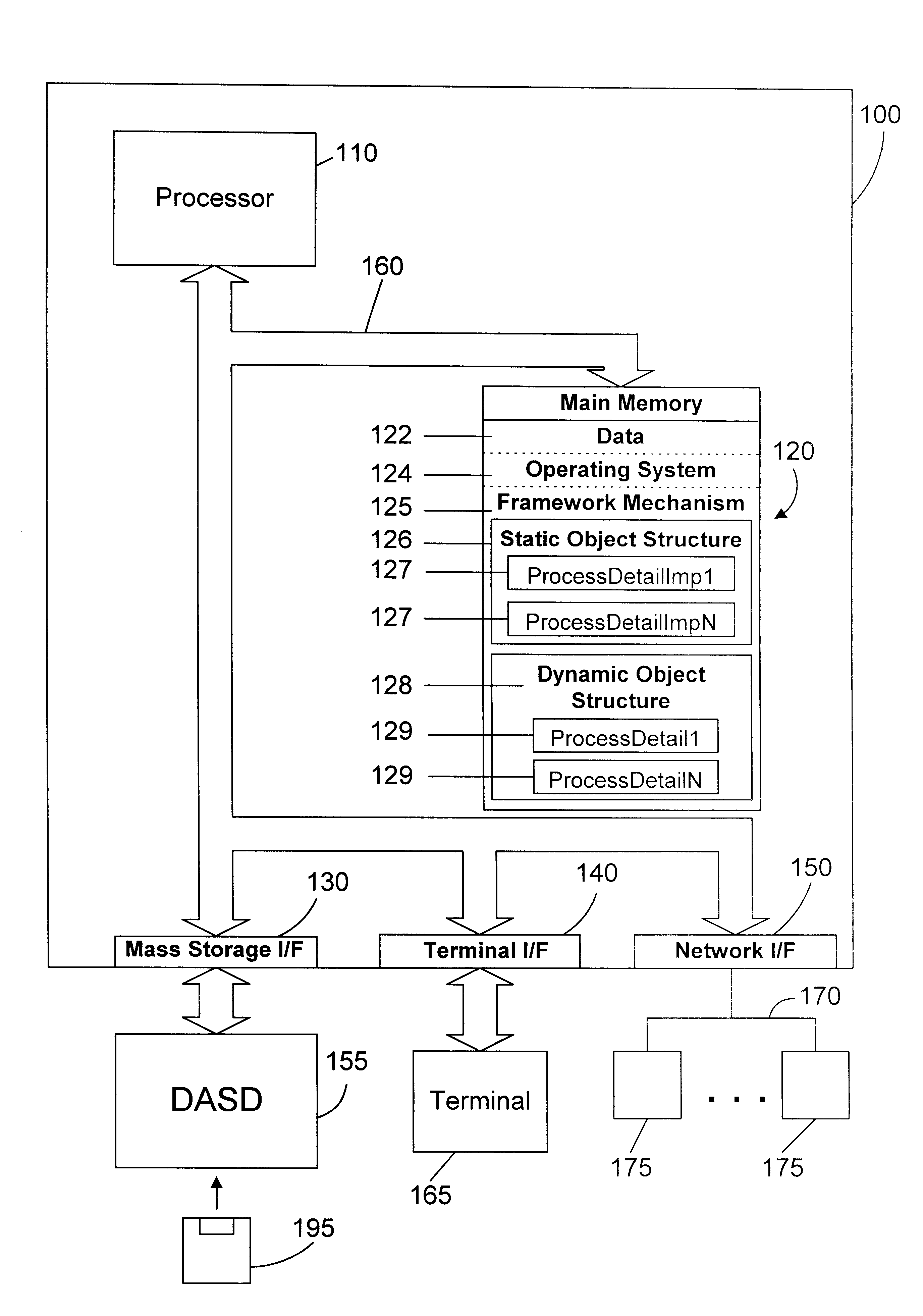
Referring to FIG. 1, a computer system 100 in accordance with the preferred embodiment is an enhanced IBM AS / 400 computer system. However, those skilled in the art will appreciate that the mechanisms and apparatus of the present invention apply equally to any computer system, regardless of whether the computer system is a complicated multi-user computing apparatus or a single user workstation. As shown in FIG. 1, computer system 100 comprises a processor 110 connected...


PUM


Abstract

In an object oriented computer system, a framework mechanism defines an infrastructure for allowing a user to couple processes in the framework together in any suitable way to define a desired process flow. A user first defines a static object structure that corresponds to the specific process flow from one process to the next. The processes in the framework may be flexibly coupled in any suitable order, so a process does not have knowledge of its predecessor or successor processes. Thus, at run-time, a process determines the next step in the process flow from the static object structure. Once a process determines its subsequent process, a client may then create the next process and invoke methods on one or more objects corresponding to the newly-created process. Each process thus determines at run-time the next step in the process flow from the static object structure that the user statically defined to configure the process flow, which defines the desired processing environment.

Description

This application is related to "Mechanism and Method for Flexible Coupling of Processes in an Object Oriented Framework", U.S. Ser. No. 09 / 162,719 filed Sep. 29, 1998, which is incorporated herein by reference.1. Technical FieldThis invention generally relates to object oriented programming and more specifically relates to a mechanism and method for defining a desired processing environment in an object oriented framework.2. Background ArtThe development of the EDVAC computer system of 1948 is often cited as the beginning of the computer era. Since that time, computer systems have evolved into extremely sophisticated devices, and computer systems may be found in many different settings. Computer systems typically include a combination of hardware, such as semiconductors and circuit boards, and software, also known as computer programs. As advances in semiconductor processing and computer architecture push the performance of the computer hardware higher, more sophisticated computer s...

Claims


Application Information

Patent Timeline
IPC IPC(8): G06F17/30G06F9/44
CPCG06F8/24G06F9/4435G06F17/30607G06F9/4493G06F16/289
Inventor CARLSON, BRENT ALLENENGSTROM, JAN OLOFGRASER, TIMOTHY JAMESLINDBLOM, ULF JESPER THOMASPROSKE, BARBARA REGINE
Owner IBM CORP
Why Eureka
Try Eureka