Mechanism and method for flexible coupling of processes in an object oriented framework

a process and object oriented technology, applied in the field of object oriented programming, can solve the problems of increasing software development costs, increasing money, and extremely powerful application software programs designed for high-performance computer systems, and achieve the effect of enhancing extensible items

Inactive Publication Date: 2001-10-23
IBM CORP
View PDF3 Cites 55 Cited by
  • Summary
  • Abstract
  • Description
  • Claims
  • Application Information

AI Technical Summary

Benefits of technology

If an ExtensibleItem object is part of a tree structure of objects, where it is attached to other ExtensibleItem objects as a parent and / or a child, the method call on one ExtensibleItem object may be delegated either upwards or downwards in the tree structure. For example, referring to FIG. 5, a very simple tree structure is provided to illustrate the delegation of method calls from one object in a tree structure to another. We assume that a class HierarchicalExtensibleItem is a subclass of ExtensibleItem that enhances ExtensibleItem by adding behavior to explicitly allow invoking methods in either a "drill up" or "drill down" fashion. HierarchicalExtensibleItem1 in FIG. 5 is an instance of the HierarchicalExtensibleItem class, and is at the top level of the tree, with two children objects HierarchicalExtensibleItem2 and HierarchicalExtensibleItem3 that are also instances of the HierarchicalExtensibleItem class. We assume that HierarchicalExtensibleItem1 supports the method "bar", and that HierarchicalExtensibleItem2 supports the method "foo". This means that these objects have one or more extensions that support these methods. In the case of "drill up", either method "foo" or "bar" could be invoked on HierarchicalExtensibleItem2. The invocation of the "foo" method on HierarchicalExtensibleItem2 delegates to the "foo" method on HierarchicalExtensibleItem2, while the invocation of "bar" delegates the "bar" up the tree (drill up) to HierarchicalExtensibleItem1. Invoking "foo" on HierarchicalExtensibleItem1 or HierarchicalExtensibleItem3 using "drill up" results in an error. When invoking a method using "drill down", if the method is found on a given HierarchicalExtensibleItem, the delegation will be to that method only, otherwise it will be invoked in "drill down" fashion (which may involve recursion) on all children of the given HierarchicalExtensibleItem, accumulating the results of the multiple method calls, if necessary. Thus, if "bar" is invoked on HierarchicalExtensibleItem1 using "drill down", it would delegate to the "bar" method on HierarchicalExtensibleItem1 and stop there. However, if "foo" were called on HierarchicalExtensibleItem1 using "drill down", the call would be delegated to "foo" on HierarchicalExtensibleItem2 and would then continue on to HierarchicalExtensibleItem3 (which would have no effect in the specific example of FIG. 5), and stop there. This concept of upwards and downwards delegation of method calls can be extended indefinitely throughout a tree structure of ExtensibleItems.
Extensible items thus provide a powerful and dynamic way to change the interface for an object at run-time so the object can acquire and tailor its domain-specific behavior as required. The concept of extensible items discussed above is the foundation upon which the present invention is built.

Problems solved by technology

As the capabilities of computer systems have increased, the application software programs designed for high performance computer systems have become extremely powerful.
Additionally, software development costs have continued to rise because more powerful and complex programs take more time, and hence more money, to produce.
A software application developed from most framework mechanisms has the order of processes and their interrelationship defined by some extent by the core functions of the framework, limiting the amount of customization available to a programmer who extends the framework.
However, more functions generally mean a more detailed implementation within the framework itself, which typically reduces the ability to adapt the framework to different circumstances.
Fewer core functions in the framework generally makes the framework more flexible, but decreases the power of the framework, putting more of a programming burden on the user that extends the framework to define a software application.
However, generating three separate frameworks for three different types of order processing essentially ignores the common features that exist in most order processing systems.
Without a mechanism for allowing process steps to be flexibly coupled together in any desired order within a framework without changing core functions of the framework, the computer industry will continue to suffer from object oriented frameworks that are limited to a specific process flow for which they were specifically designed.

Method used


Image

  • Mechanism and method for flexible coupling of processes in an object oriented framework
  • Mechanism and method for flexible coupling of processes in an object oriented framework
  • Mechanism and method for flexible coupling of processes in an object oriented framework

Examples


Embodiment Construction

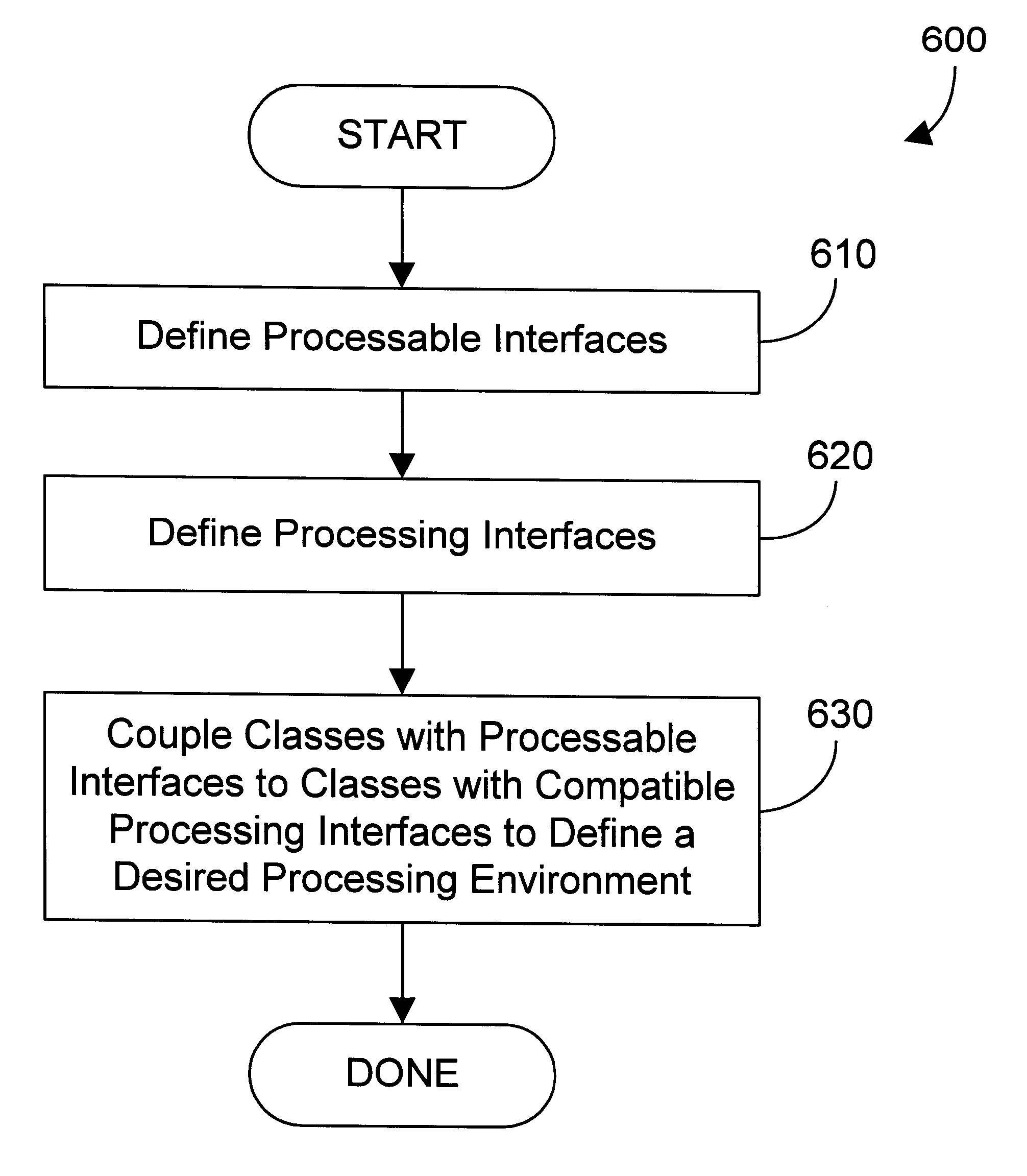
According to a preferred embodiment of the present invention, a mechanism and method provide for flexible coupling of processes in an object oriented framework without changing the core functions of the framework. Interfaces are provided that allow a class to be defined in a way that allows appropriate placement of the class relative to the other classes in the framework to achieve a desired processing environment from extending the framework.

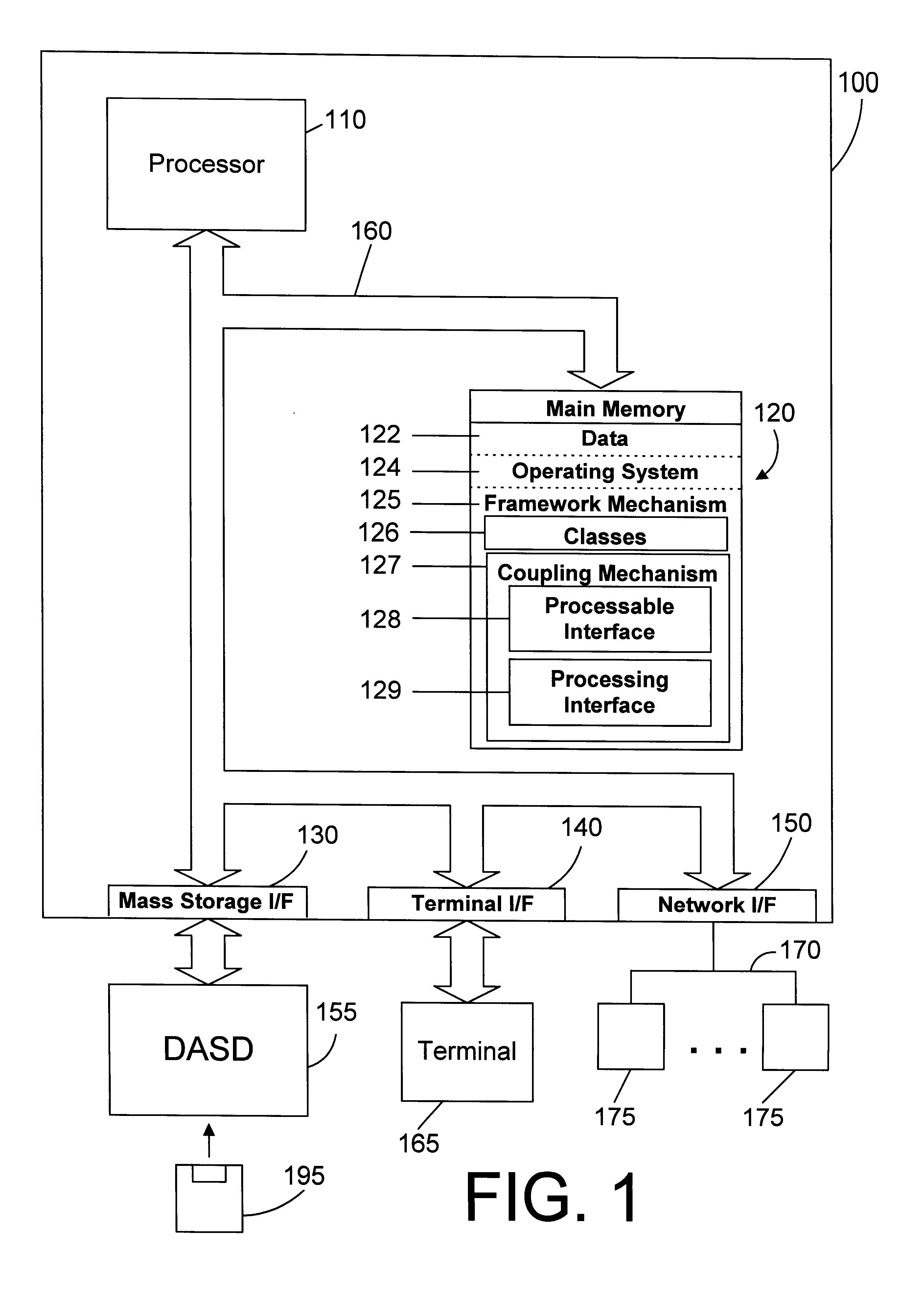
Referring to FIG. 1, a computer system 100 in accordance with the preferred embodiment is an enhanced IBM AS / 400 computer system. However, those skilled in the art will appreciate that the mechanisms and apparatus of the present invention apply equally to any computer system, regardless of whether the computer system is a complicated multi-user computing apparatus or a single user workstation. As shown in FIG. 1, computer system 100 comprises a processor 110 connected to a main memory 120, a mass storage interface 130, a terminal interface 140,...


PUM


Abstract

In an object oriented computer system, a framework mechanism defines a mechanism that separates the ability to complete a process from the results of that process. A task is defined in the framework in terms of a sequence of processes. The framework includes a coupling mechanism for flexibly coupling any of these processes together in any suitable order to define the run-time behavior of the framework without changing the core functions of the framework. The coupling mechanism includes the definition of a processable interface and a processing interface. A particular process generally takes detail information as input and produces detail information that is used in a subsequent process. The detail information input into a process is said to be "processable", and therefore implements the "processable" interface. The detail information output from a process is said to be "processing" detail that is output to the next process, and therefore implements the processing interface. Thus, an object that uses "shippable" detail information as input through its processable interface generates corresponding "shipping" detail information for each shippable detail, which is output to one or more subsequent processes via the processing interface. A particular processable can be associated with any processing interface that supports the processable interface. In other words, any process-related class in the framework can be coupled to any other process-related class, provided one class has a processing interface that corresponds to the processable interface of the subsequent class. In this manner, classes in the framework mechanism can be flexibly coupled together in any suitable order or fashion to accommodate a great variety of different configurations. The framework mechanism therefore provides a high degree of implementation while maintaining the ability to achieve a high degree of customization.

Description

1. Technical FieldThis invention generally relates to object oriented programming and more specifically relates to a mechanism and method for coupling processes in an object oriented framework to create a desired processing environment.2. Background ArtThe development of the EDVAC computer system of 1948 is often cited as the beginning of the computer era. Since that time, computer systems have evolved into extremely sophisticated devices, and computer systems may be found in many different settings. Computer systems typically include a combination of hardware, such as semiconductors and circuit boards, and software, also known as computer programs. As advances in semiconductor processing and computer architecture push the performance of the computer hardware higher, more sophisticated computer software has evolved to take advantage of the higher performance of the hardware, resulting in computer systems today that are much more powerful than just a few years ago.Computer systems ty...

Claims


Application Information

Patent Timeline
Patent Type & Authority Patents(United States)
IPC IPC(8): G06F17/30G06F9/44
CPCG06F17/30607G06F8/24G06F9/4435G06F9/4493G06F16/289
Inventor CARLSON, BRENT ALLENGRASER, TIMOTHY JAMESLINDBLOM, ULF JESPER THOMASPERNBECK, TORBJORNREASON, SIMON PAUL
Owner IBM CORP
Why Eureka
Try Eureka