Compressor intercooler unloader arrangement

a compressor and intercooler technology, applied in the direction of positive displacement liquid engines, pump control, pump components, etc., can solve the problems of overheating the motor and shorten the life of the motor, and achieve the effect of extending the life of the compressor drive motor and removing the heat buildup of the compressor motor

Inactive Publication Date: 2001-03-20
WESTINGHOUSE AIR BRAKE CO
View PDF5 Cites 42 Cited by
  • Summary
  • Abstract
  • Description
  • Claims
  • Application Information

AI Technical Summary

Benefits of technology

Another objective of the invention is to eliminate compressor motor heat buildup by eliminating the possibility of the motor starting against an air load retained in the intercooler.
A further

Problems solved by technology

The motor, in turn, requires an increase in current

Method used


Image

  • Compressor intercooler unloader arrangement
  • Compressor intercooler unloader arrangement

Examples


Embodiment Construction

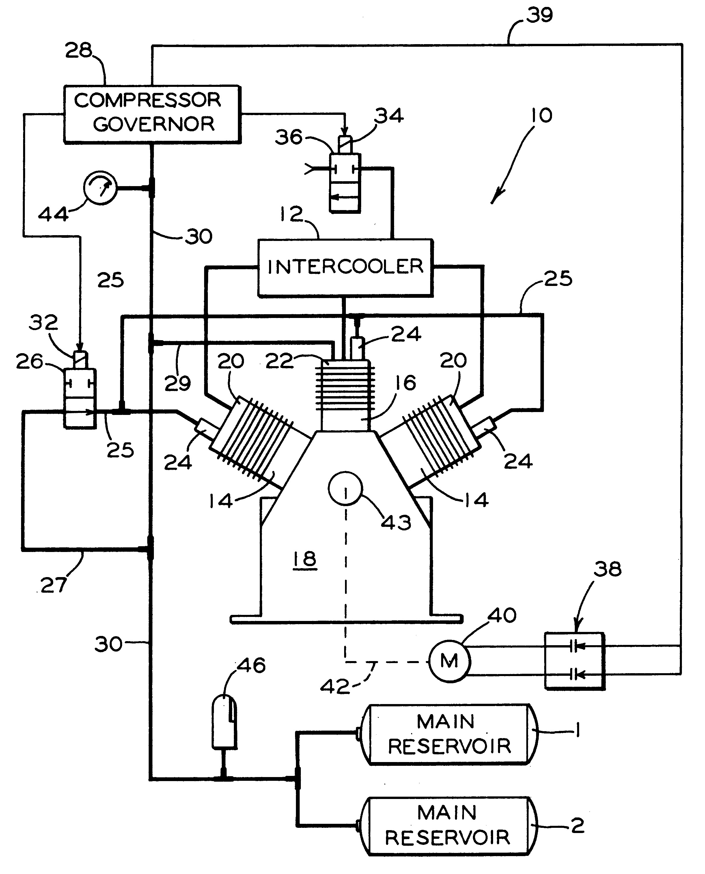
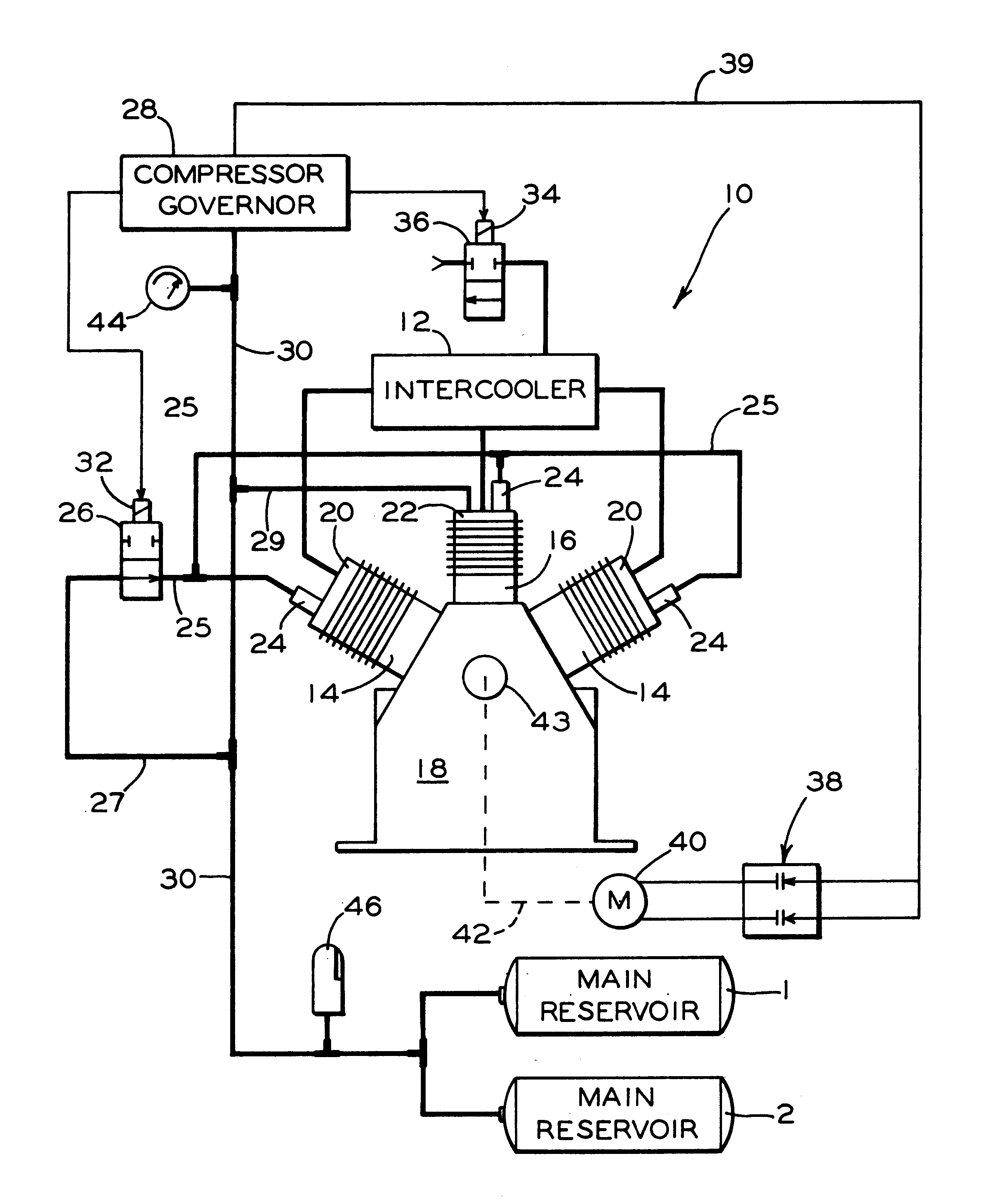
Referring now to the drawing FIGURE, a pneumatic and electrical system 10 is shown for rapidly exhausting an intercooler (IC) 12 connected in fluid.communication between a high pressure cylinder 16 and two low pressure cylinders 14 of an air compressor 18. As explained earlier, the intercooler cools low pressure air issuing from low pressure heads 20 of cylinders 14 before such air reaches high pressure head 22 of cylinder 16. The cooling action is performed by heat exchange tubes (not shown) of the intercooler receiving pressurized air from cylinders 14.

In the FIGURE, each cylinder head (20 and 22) of compressor 18 is shown provided with an unloader valve 24 for unloading (exhausting) air from the cylinders of the compressor. These valves are shown commonly and pneumatically connected via unloader lines 25 to a magnet valve 26 pneumatically connected, in turn, by a pipe 27 to main reservoirs 1 and 2 of a locomotive.

The high pressure cylinder 16 and head 22 supply compressed air to ...


PUM


Abstract

Apparatus for rapidly unloading air pressure in an intercooler to atmosphere when a compressor pneumatically connected to the intercooler is unloaded. The apparatus includes a governor pneumatically connected to a reservoir, that, in turn, is connected to receive pressurized air from the air compressor. The governor has a pressure sensing device operable to order unloading of the compressor when air pressure level in the reservoir tank reaches a preset level. An electrically operated valve is pneumatically connected to the intercooler and connected electrically to the pressure sensing device of the governor, with the electrically operated valve being effective to exhaust air pressure in the intercooler when the valve receives an unload signal from the pressure sensing device. The compressor is driven, by an electrical motor having one or more speed configurations, with transition occurring between one configuration and another when the compressor is unloaded. The electrically operated valve is effective to unload the intercooler at the time of speed configuration transition to reduce undue motor and electrical contactor heat and thus increase life expectancy of the motor and contactors.

Description

The present invention relates generally to air compressors used on locomotives, and particularly to a pneumatic and electrical circuit arrangement that permits rapid unloading of an intercooler unit pneumatically connected between low pressure heads and a high pressure head of a compressor.U.S. Pat. No. 5,106,270 to Goettel et al discloses a two stage compressor and intercooler / aftercooler arrangement for providing pressurized air for the operation of brakes and other devices on locomotives and trains of railway cars connected to such locomotives. As disclosed in the patent, the compressor has two low pressure cylinders and a high pressure cylinder that develop air pressure. Between the high pressure cylinder and cylinder head and the low pressure cylinders and their heads are located intercoolers that cool the pressurized air generated in the low pressure cylinders before such air is sent on to the high pressure cylinder for high pressure air development. A single intercooler core ...

Claims


Application Information

Patent Timeline
IPC IPC(8): F04B39/06F04B25/00
CPCF04B25/00F04B39/06
Inventor WAGNER, DANIEL G.CUNKELMAN, BRIAN L.GOETTEL, WALTER E.
Owner WESTINGHOUSE AIR BRAKE CO
Why Eureka
Try Eureka