Lower sideband modulation distortion cancellation

Inactive Publication Date: 2001-03-20
CRL SYST
View PDF4 Cites 39 Cited by
  • Summary
  • Abstract
  • Description
  • Claims
  • Application Information

AI Technical Summary

Problems solved by technology

Therefore, in any of the prior art peak limiting systems discussed, the lower sideband (representing distortion induced by the peak limiting process) is

Method used


Image

  • Lower sideband modulation distortion cancellation
  • Lower sideband modulation distortion cancellation
  • Lower sideband modulation distortion cancellation

Examples


first embodiment

The first embodiment is the more economical system because it requires very little extra arithmetic computations. However, it is not frequency selective so it can increase distortion at low frequencies where no overshoot control is needed.
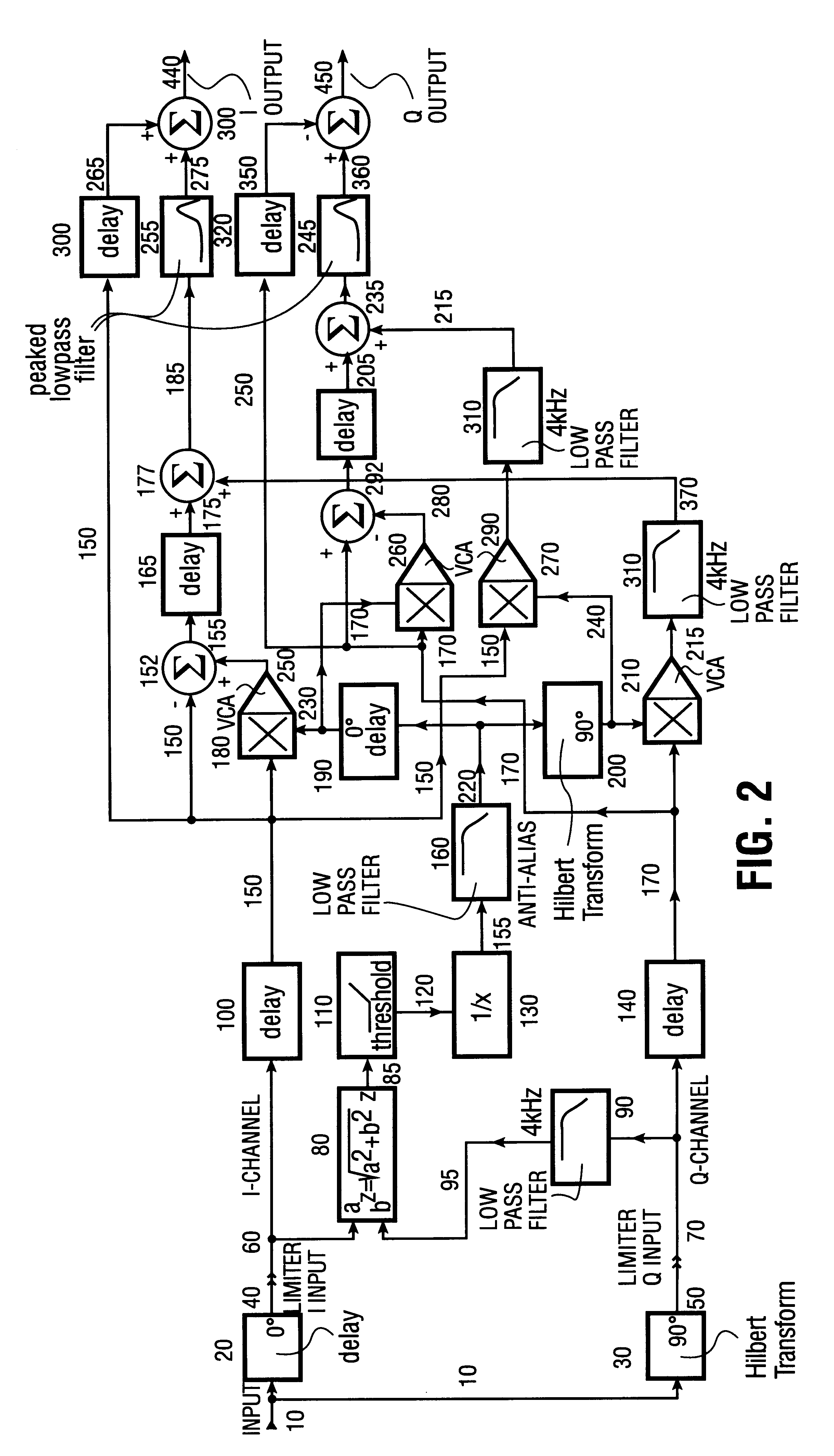
second embodiment

The second embodiment is more expensive than the first embodiment because it requires two filters. However, unlike the first embodiment, it does not increase distortion at low frequencies because the filter provides extra gain only where needed to control overshoot.

By changing the sign of the summation of the multiplier that processes the Hilbert transform of the input signal a system that produces only the lower sideband of the modulation distortion can be produced. While much more audible than the upper sideband, it is useful to use this to prevent the system from producing out-of-band spectral components.

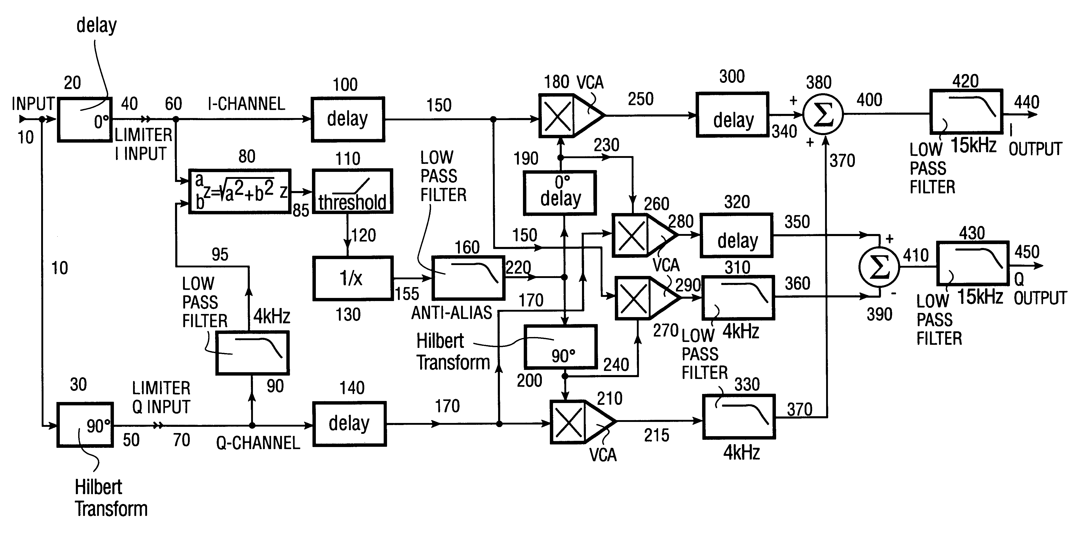
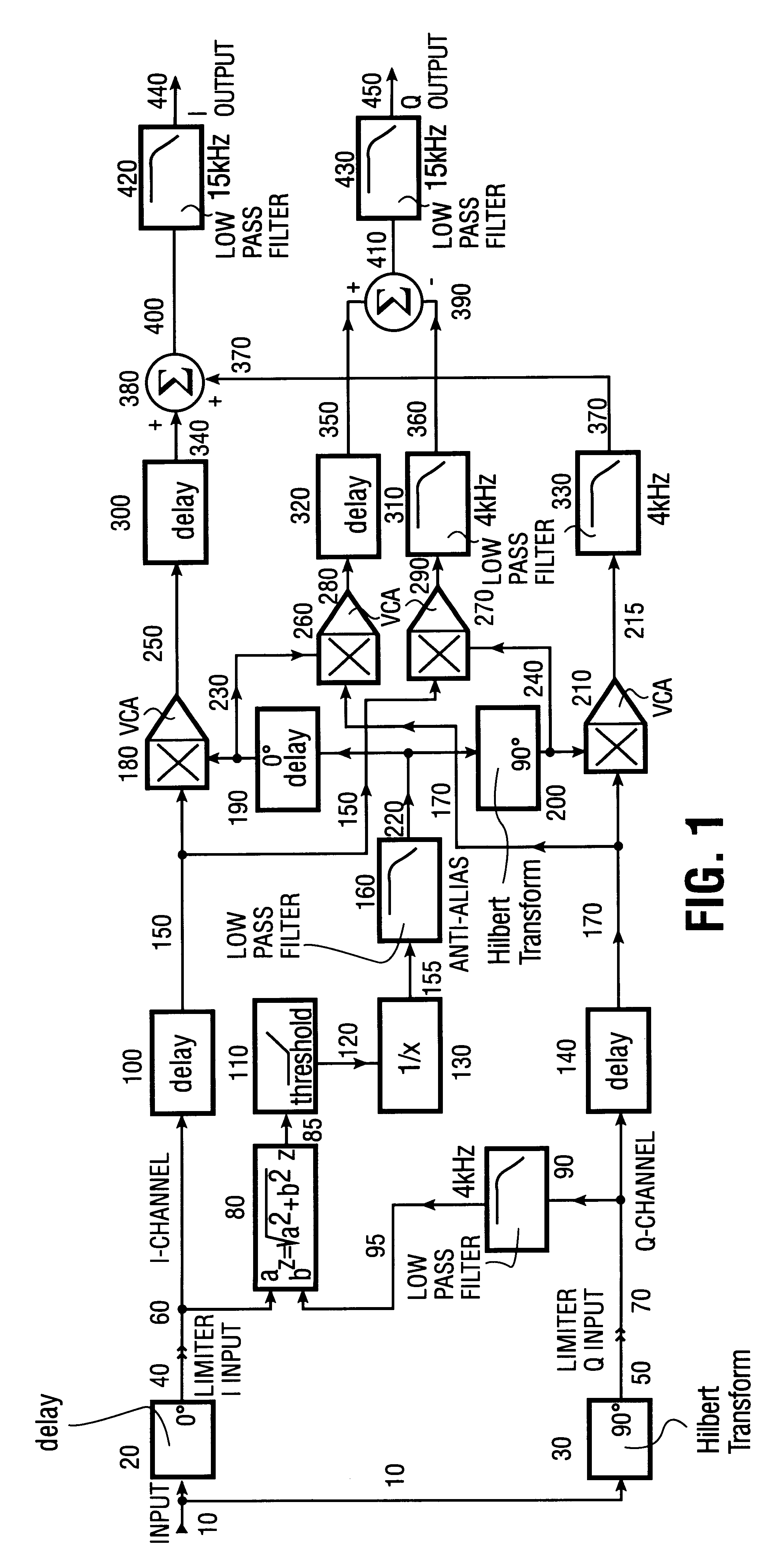
first embodiment (system of fig.1)

FIRST EMBODIMENT (SYSTEM OF FIG. 1)

Referring to FIG. 1, the input signal on line 10 is applied to Hilbert transformer 30 and delay 20. All physical Hilbert transformers have time delay, the time delay in delay 20 is equal to the time delay in Hilbert transformer 30 plus the time delay in lowpass filter 90.

Almost any Hilbert transformer realization can be used for transformer 30. (U.S. Pat. No. 4,495,643 discusses this in more detail.) However, the higher audio quality is achieved by a linear-phase realization because this allows delay 20 to preserve the shape of the waveform on line 10. Such a realization is generally only practical in the sample-data domain and can be achieved by an antisymmetrical Finite Impulse Response (FIR) digital filter. The Parks, McClellan, and Rabiner algorithm can compute the tap weights for such a filter. (Program EQFIR in PARKSMC.F, Oct. 27, 1997, pp. 1-12.) Such filters have a bandpass characteristic, and a bandwidth wide enough for high-quality audio ...


PUM


Abstract

An audio peak limiter in which the lower sideband of the modulation distortion spectrum is canceled. The peak limiter is realized by multiplying the input signal by a control signal. The Hilbert transform of the control signal is multiplied by the Hilbert transform of the input signal and the outputs of the two multipliers are added. This cancels the lower sideband of the modulation process. Various filters can be added to eliminate aliasing in digital realizations, to band-limit the output signal, and to control peak overshoot.

Description

1. Field of the InventionThe invention relates to audio peak limiters and other audio control systems, more particularly to the cancellation of lower sideband modulation distortion in such systems.2. Prior ArtFast audio peak limiters include simple peak clippers, radio frequency clippers, Hilbert transform limiters as disclosed in U.S. Pat. No. 4,495,643, delay-line limiters, and others. Some of these operate directly on an input audio signal such as the simple peak clipper, which replaces any positive or negative instantaneous level exceeding a preset positive or negative threshold with the corresponding threshold value. Other peak limiters operate by multiplying a control signal by the input signal. All systems that operate directly on the signal have equivalent systems (producing the same outputs) that multiply the input signal by a control signal. U.S. Pat. No. 5,168,526 discusses how such an equivalent system can be synthesized.Any system in which the input signal is multiplied...

Claims


Application Information

Patent Timeline
IPC IPC(8): H03G9/12H03G11/00H03G9/00
CPCH03G9/12H03G11/00
Inventor ORBAN, ROBERT
Owner CRL SYST
Why Eureka
Try Eureka