Apparatus to control multiple parallel batteries to share load current

Inactive Publication Date: 2001-03-27
SPACE SYST LORAL INC
3 Cites 51 Cited by

AI-Extracted Technical Summary

Problems solved by technology

Such prior techniques ar...

Benefits of technology

An object of the present invention is to provide a highly efficient ap...

Abstract

Circuit apparatus for controlling a plurality of parallel connected batteries to equally share a common load is shown that includes an n parallel batteries connected to a common load element through a load current monitor that monitors the current through the load element, a battery current monitor for each battery, and a plurality of DC/DC converter circuits having outputs connected in series with each battery respectively. The load current output signal of the load current monitor is scaled down by 1/n, where n is the number of batteries, by a scale down amplifier circuit and distributed as a reference voltage to summing circuits where the scaled down load current is compared to the output of the battery current monitors. The outputs of the summing circuits are respectively connected as control signals to each of the DC/DC converters that are connected to each battery. Each DC/DC converter circuit adjusts it's output voltage to regulate the battery currents to I1 . . . In of each of the n batteries to be equal to the reference voltage from the load current monitor.

Application Domain

Charge equalisation circuitParallel/serial switching +5

Technology Topic

Image

  • Apparatus to control multiple parallel batteries to share load current
  • Apparatus to control multiple parallel batteries to share load current

Examples

  • Experimental program(1)

Example

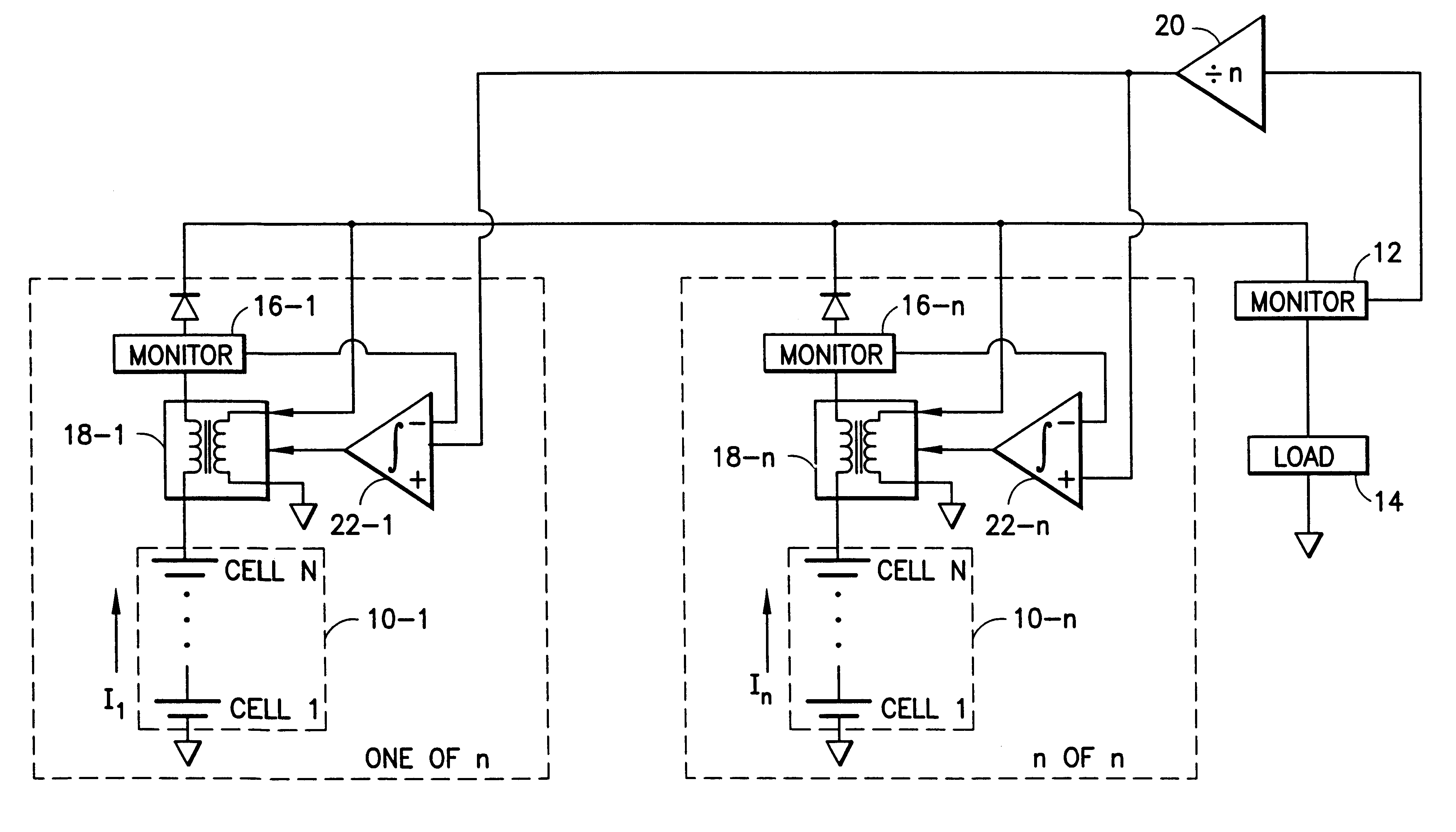
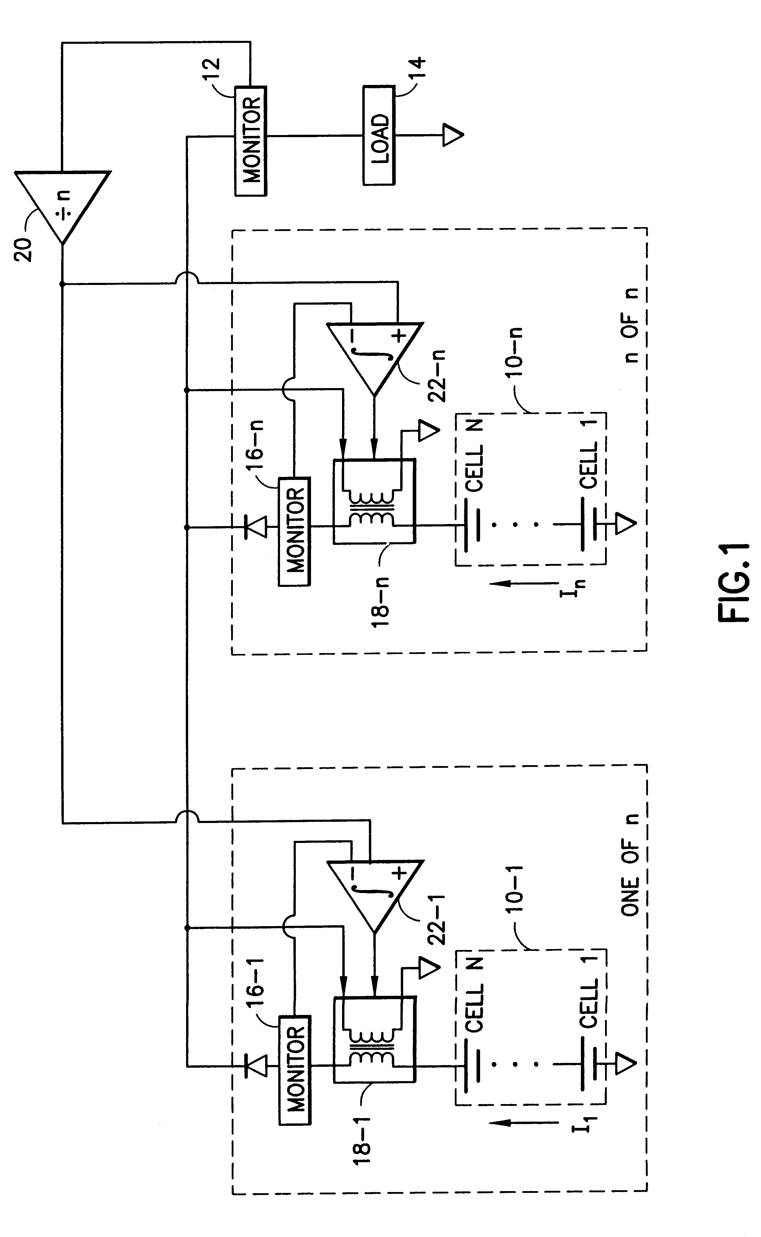
Referring to FIG. 1, an embodiment of the present invention is shown that includes an architecture of n parallel batteries 10-1 . . . 10-n, each of which consist of N number of series connected battery cells where n and N may or may not be the same number. FIG. 1 also shows a load current monitor 12 that monitors the current through a load element 14, a battery current monitor 16-1 . . . 16-n for each battery, and n number of DC/DC converter circuits 18-1 . . . 18n having outputs connected in series with each battery 10-1 . . . 10-n respectively. Current sharing of the batteries is accomplished as follows: The load current output signal of the load current monitor 12 is scaled by 1/n, where n is the number of batteries, by a scale down amplifier circuit 20 and distributed as a reference voltage to summing circuits 22-1 . . . 22-n where the scaled down load current is compared to the output of the battery current monitors 16-1 . . . 16m. The outputs of the summing circuits 22-1 . . . 22-n are respectively connected as control signals to each of the DC/DC converters 18-1 . . . 18-n that are connected to each battery 10-1 . . . 10-n. Each DC/DC converter 18-1 . . . 18-n adjusts it's output voltage to regulate the battery currents I1 . . . In of each of the n batteries to be equal to the reference voltage from the load current monitor 12. The DC/DC converters 18-1 . . . 18-n are typically either n+1 redundant or primary/backup. Each of the DC/DC converter circuit's 18-1 . . . 18-n output voltage will typically be the difference between the bus voltage and the battery voltage. Thus, each of the batteries 10-1 . . . 10-n share the load element 14 equally. A secondary voltage loop can also be added to use the DC/DC converters 18-1 . . . 18n to regulate the bus voltage.
It should be understood that the foregoing description is only illustrative of the invention. Various alternatives and modifications can be devised by those skilled in the art without departing from the invention. Accordingly, the present invention is intended to embrace all such alternatives, modifications and variances which fall within the scope of the appended claims.

PUM

no PUM

Description & Claims & Application Information

We can also present the details of the Description, Claims and Application information to help users get a comprehensive understanding of the technical details of the patent, such as background art, summary of invention, brief description of drawings, description of embodiments, and other original content. On the other hand, users can also determine the specific scope of protection of the technology through the list of claims; as well as understand the changes in the life cycle of the technology with the presentation of the patent timeline. Login to view more.

Similar technology patents

Low friction chain

ActiveUS20080020882A1Reduce wearCombustion efficiency be improveDriving chainsEdge surfaceLow friction
Owner:TSUBAKIMOTO CHAIN CO

Insulator cleaning robot

Owner:STATE GRID INTELLIGENCE TECH CO LTD

Classification and recommendation of technical efficacy words

  • Reduce wear
  • High efficiency

Denture

InactiveUS6139322ASuperior physical and aesthetic characteristicReduce wearImpression capsArtificial teethInterpenetrating polymer networkDentures
Owner:DENTSPLY RES DEVMENT
Why Eureka
Try Eureka