Moving-weight, dynamic balancing apparatus for a rotary machine, in particular for industrial fans

a rotary machine and moving weight technology, applied in the direction of wind motor control, non-positive displacement fluid engine, liquid fuel engine components, etc., can solve the problems of vibration generated by such machines, gradual unbalance of the rotor, and exposure to the risk of particles or blowing matter deposited

Inactive Publication Date: 2001-04-03
FLAKT SOLYVENT VENTEC
View PDF20 Cites 52 Cited by
  • Summary
  • Abstract
  • Description
  • Claims
  • Application Information

AI Technical Summary

Benefits of technology

The object of the invention is consequently to remedy the above-specified drawbacks, and to propose novel, moving-weight, dynamic balancing apparatus for rotary machines in which correction force control can be performed accurately.
Another object of the invention seeks to propose novel balancing apparatus that is particularly simple to implement in terms of extra equipment, and that can be done at low cost.

Problems solved by technology

One of the major problems of large capacity turbo-machines as described above relates to the vibration that such machines can generate, in particular at the bearings.
In most cases, the origins of such vibration stem from rotor unbalance.
For industrial fans of large capacity, e.g. of the order of 100 kW to 10,000 kW, their normal operating conditions necessarily imply that an unbalanced state of the rotor appears gradually or suddenly.
Consequently they are commonly exposed to the risk of particles or blown matter being deposited on or by the blades of the fan, to progressive wear of the blades of the fan due to the various corrosion effects of the fluids or gases passing through the fan, or indeed to deformation due to sudden temperature variations.
The deposition of matter (clogging) on the blades of the fan also generally takes place in gradual and non-uniform manner on the various blades of the fan, thereby giving rise to a first rotor-unbalancing effect.
In certain applications, for example in cement works, this first rotor-unbalancing effect can be accompanied by a second unbalancing phenomenon that is much more sudden, being caused by one or more blocks of material that were previously stuck to the blades becoming detached therefrom suddenly.
This second phenomenon gives rise to large and violent unbalance of the rotor which is particularly dangerous for large-capacity appliances in which blade diameter can easily be three meters (m) and the speed of rotation at least 1000 revolutions per minute (rpm).
In addition, the operations of cleaning or rebalancing the rotor are lengthly and particularly difficult.
Industrially and economically speaking, the downtime of the fan represents a large expense that is difficult to accept.
Such apparatus provides a genuine contribution to controlling rotor unbalance, however it nevertheless suffers from a certain number of drawbacks associated in particular with the impossibility of avoiding the particularly tough and extreme operating conditions in which industrial fans must necessarily operate.
Thus, the extreme temperature variation conditions to which industrial fans are subject can have a negative effect on the accuracy with which balancing or rebalancing of industrial fan rotors is performed when balancing is done by means of fluid vaporization / condensation.
Also, since the correction of fan unbalance relies on transferring fluid from a hot point to a condensation cold point, the accuracy with which such apparatus can be controlled is limited because of the similarly limited number of cooling chambers around the periphery of the ring.
In other words, rotor rebalancing is performed at discrete balancing zones at the periphery of the balancing ring, and not at any point chosen continuously around the entire periphery of the ring, thereby leading to relatively inaccurate balancing.
Finally, it should be observed that a balancing system making use of a fluid circuit is relatively fragile since the circuit must be perfectly fluid-tight even though the usual operating conditions of industrial fans imply that ambient conditions are particularly difficult and corrosive.
It also turns out that the balancing capacity of fluid systems is limited to industrial fans of small capacity.
Such solutions are not suitable for balancing large masses or for operating in difficult environmental conditions.

Method used


Image

  • Moving-weight, dynamic balancing apparatus for a rotary machine, in particular for industrial fans
  • Moving-weight, dynamic balancing apparatus for a rotary machine, in particular for industrial fans
  • Moving-weight, dynamic balancing apparatus for a rotary machine, in particular for industrial fans

Examples


Embodiment Construction

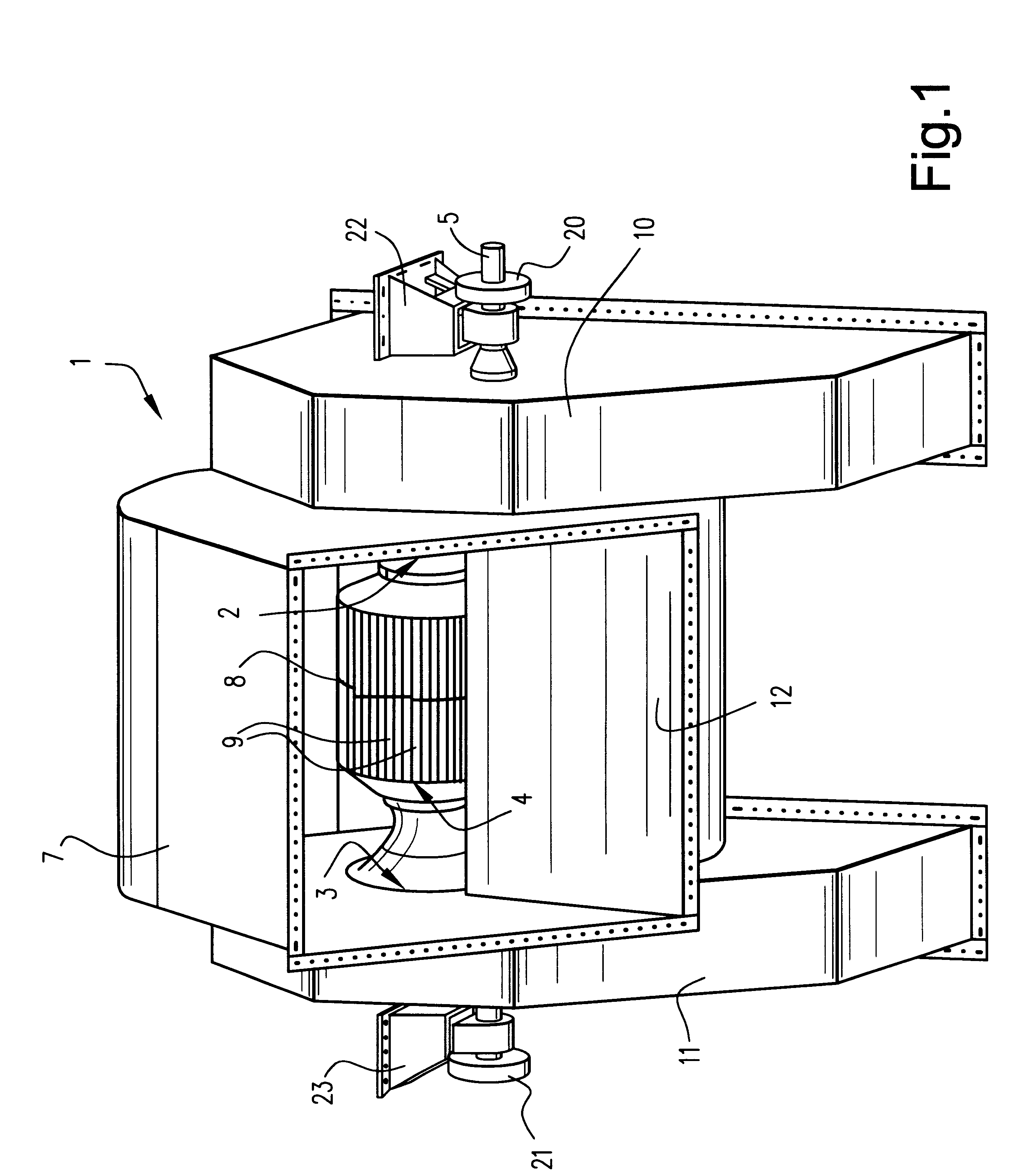
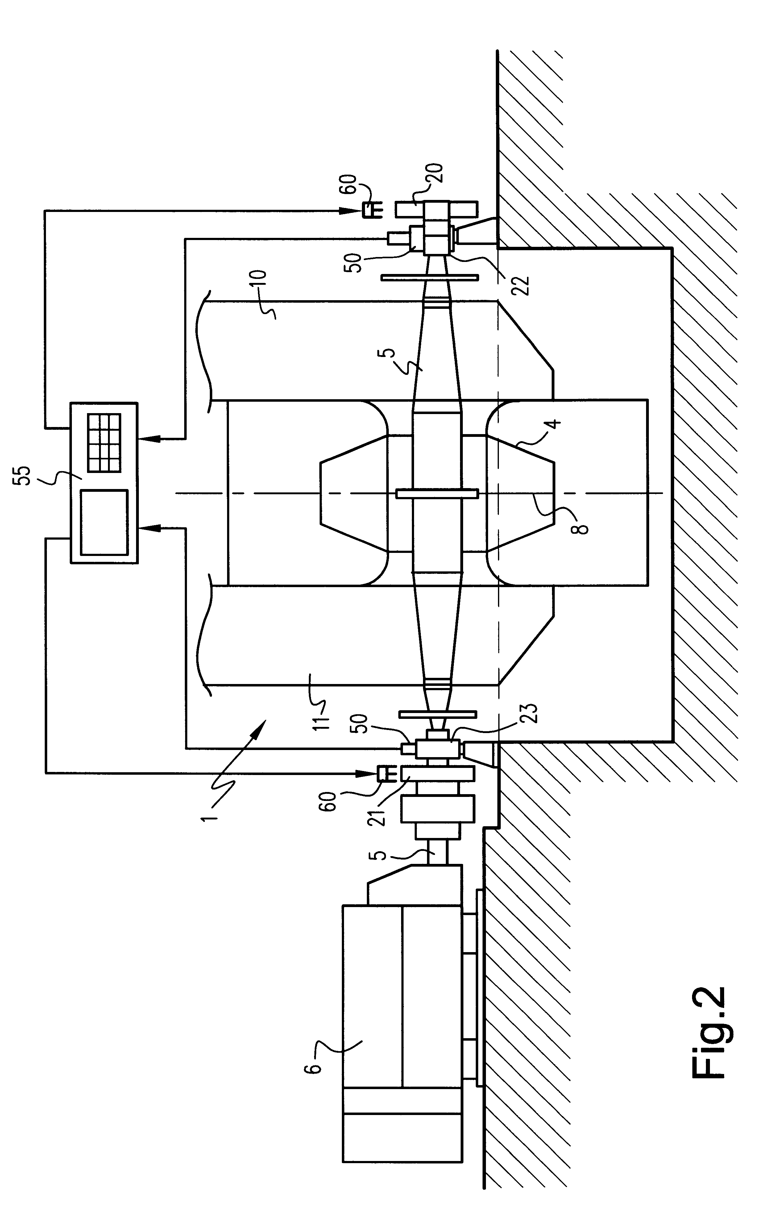
FIG. 1 is a general perspective view of an industrial fan of the dual-flow centrifugal type having at least two fluid inlets 2, 3 disposed on either side of a fan wheel 4 which is mounted and supported in rotation on a rotary shaft 5 itself suitable for being rotated by means of a drive device (FIG. 2) such as an electric motor 9, for example. The fan wheel 4 forming the rotor is mounted in a structure provided with an outer cowling 7 and including, in conventional manner, a central disk 8 which may be notched and whose lateral faces are provided with a series of vanes 9 covered by plates of varying profile in a manner appropriate to the type of centrifugal fan and to the characteristics of the fluid to be blown.

There are generally two inlets 2, 3 and they form the suction units of the centrifugal fan 1.

At the suction units, the centrifugal fans 1 are preferably fitted with flow regulation systems disposed upstream from the fan wheel and disposed in suction chambers 10, 11 associate...


PUM


Abstract

A moving-weight, dynamic balancing apparatus for a rotary machine, in particular an industrial fan, having a rotary shaft, and at least one rotor carried by the rotary shaft and provided with main rotor bearings to allow rotary movement thereof. The balancing apparatus includes at least one moving-weight balancing unit is carried by the rotary shaft, and at least one monitoring and correcting system having a drive assembly. The at least one monitoring and correcting system monitors and corrects the unbalanced state of the rotor, and acts continuously on the at least one moving-weight balancing unit when the rotor is rotating to monitor and correct for rotor unbalance. The at least one moving-weight balancing unit has at least two balancing masses mounted to be movable under drive from the drive assembly controlled by the monitoring and correction system. The at least one moving-weight balancing unit is situated axially at a distance from the rotor to be balanced beyond the main rotor bearings, and includes a ring and at least one guide assembly. The at least two balancing masses include respective carriages that are moveable in the ring, guided by the at least one guide assembly, independently of each other along trajectories that form closed circuits around the rotary shaft under drive from the drive assembly associated with each of said at least two balancing masses.

Description

The present invention relates to the general technical field of moving-weight, dynamic balancing apparatuses for rotary machines, in particularly for turbo-machines such as industrial fans.The present invention relates to moving-weight, dynamic balancing apparatus for a rotary machine, in particularly an industrial fan, the machine including at least one rotor carried by a rotary shaft, the apparatus having at least one moving-weight balancing unit carried by said shaft and situated axially at a distance from the rotor to be balanced, and at least one system for monitoring and correcting the unbalanced state of the rotor, said system being suitable for acting continuously on the balancing unit(s) when the rotor is rotating to monitor and correct rotor unbalance, the one moving-weight balancing unit comprising at least two balancing masses mounted to be movable under drive from drive means controlled by the monitoring and correction system.The present invention also relates to an ind...

Claims


Application Information

Patent Timeline
Patent Type & Authority Patents(United States)
IPC IPC(8): F16F15/00F16F15/36F24F7/00
CPCF16F15/36F24F7/00Y10T464/50Y10S416/50F16F15/322
Inventor HUGBART, JEAN-PAULGODICHON, ALAIN F. E.TRIONFETTI, GIANNI
Owner FLAKT SOLYVENT VENTEC
Why Eureka
Try Eureka