Laser optical apparatus

a laser optical and laser technology, applied in the field of laser optical apparatuses, can solve the problems of long process time required, glass substrate cannot withstand a heating process, low uniformity of the process effect on the surface,

Inactive Publication Date: 2001-04-03
SEMICON ENERGY LAB CO LTD
View PDF20 Cites 148 Cited by
  • Summary
  • Abstract
  • Description
  • Claims
  • Application Information

AI Technical Summary

Problems solved by technology

A glass substrate can not withstand a heating process at temperatures as high as 600.degree. C. or more or 700.degree. C. or more.
This results in problems including low uniformity of the effect of the process in a surface and a long period of time required for the process.
Especially, common source beams result in a significant problem from the viewpoint of uniformity of the effect of processing when used as they are because they have non-uniform distribution of light intensity.
In the case of the conventional multi-cylindrical lens as described above, since there is an angle at the ends of each cylindrical lens (boundaries between itself and other cylindrical lenses), beams have been scattered at such regions, which has resulted in optical loss.
This means that the laser beams can not be effectively utilized and the beam intensity is reduced.

Method used


Image

  • Laser optical apparatus
  • Laser optical apparatus
  • Laser optical apparatus

Examples


Embodiment Construction

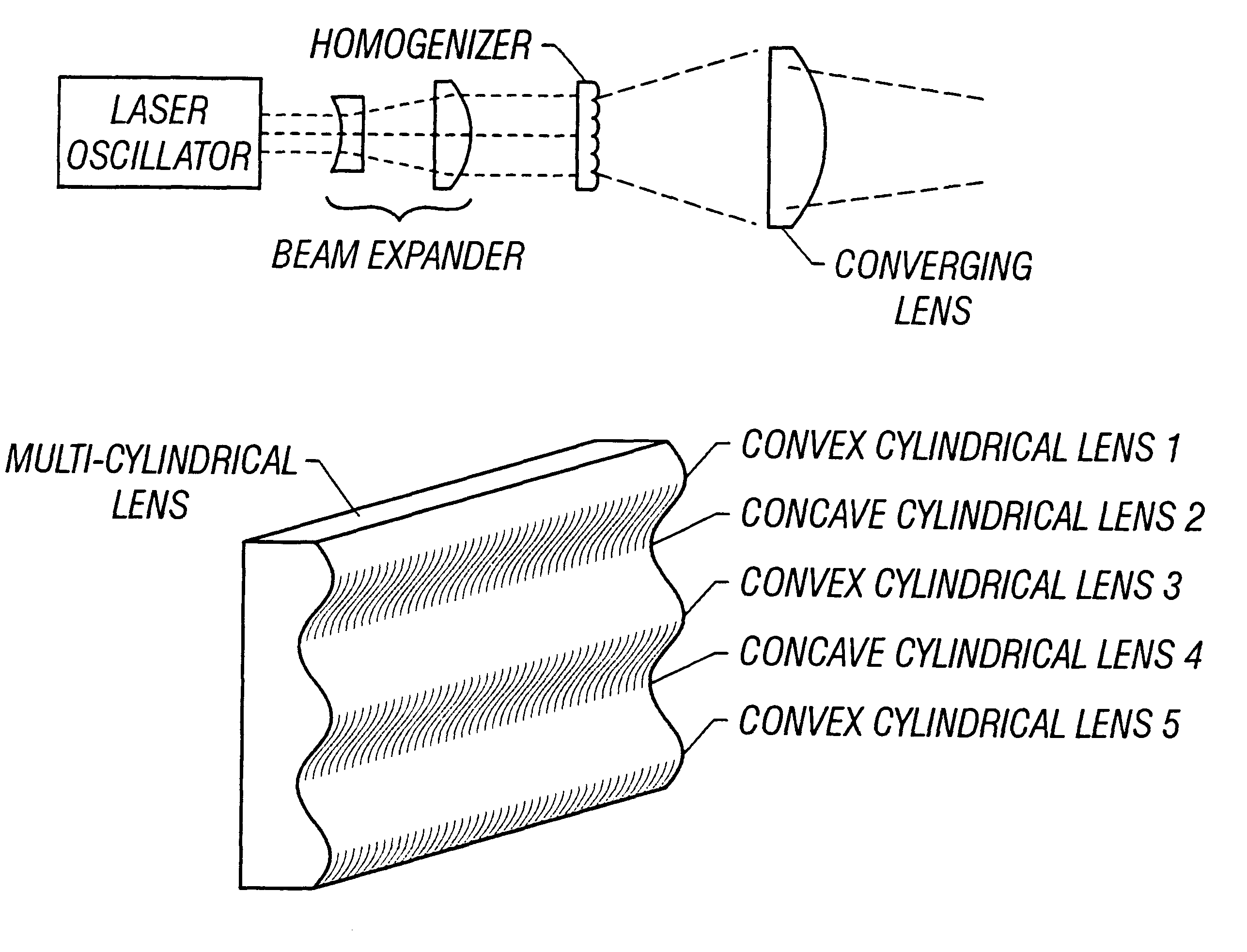
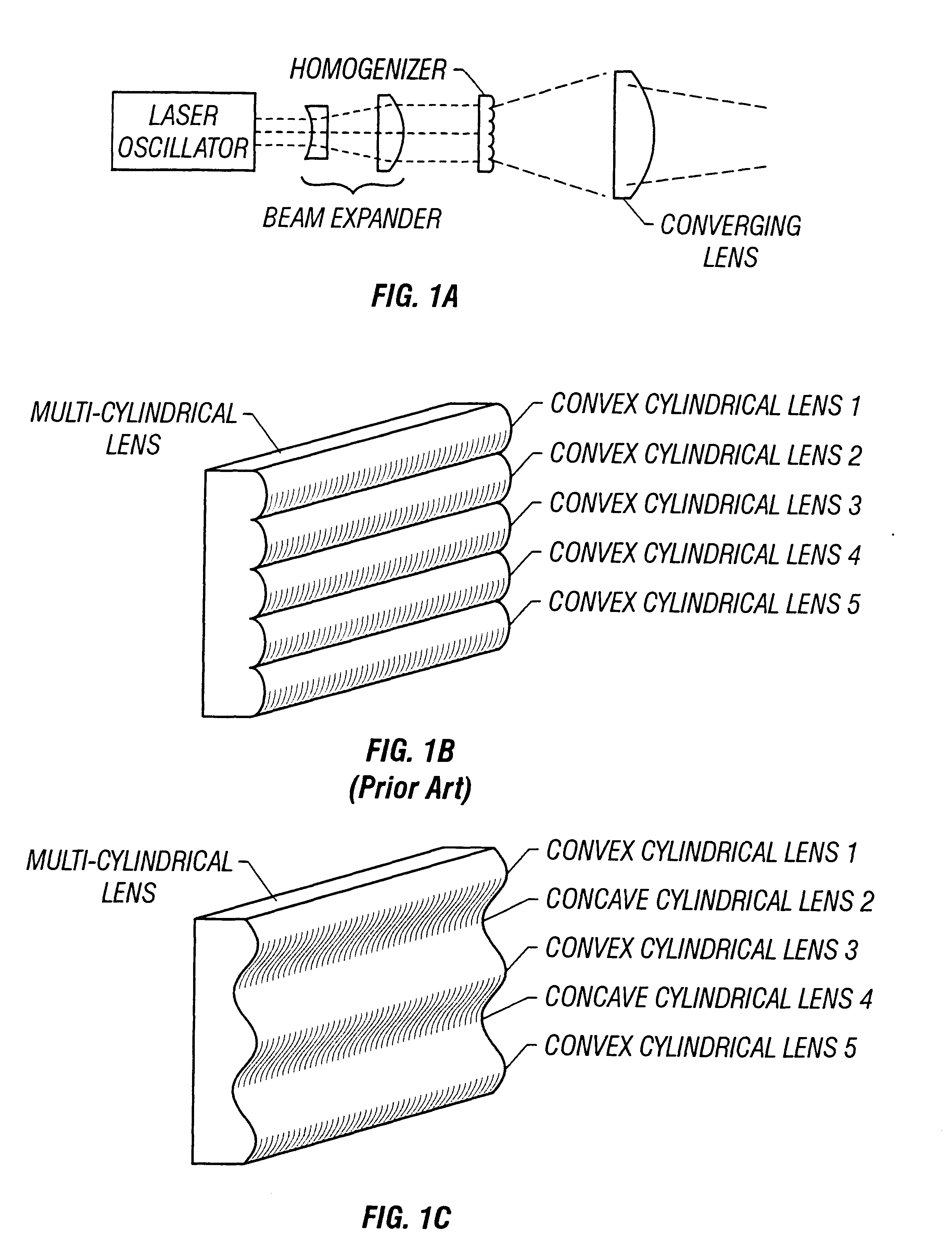
An optical system of an embodiment of the present invention will now be described. A laser irradiation apparatus according to the present embodiment has the same basic configuration as that shown in FIG. 1A. The shape of a laser beam before incidence upon a homogenizer is expressed by 6 cm.times.5 cm. In this embodiment, a multi-cylindrical lens is used as the homogenizer. Here, only the multi-cylindrical lens will be described.

In the configuration shown in this embodiment, the multi-cylindrical lens is formed by arranging six concave cylindrical lenses (having a width of 5 mm) and five convex cylindrical lenses (having a width of 5 mm) alternately to divide an incident beam into about ten beams. The length of the cylindrical lenses in the longitudinal direction thereof is 7 cm. The multi-cylindrical lens is made of quartz.

In the present embodiment, the length of a liner laser beam that is finally projected is 12 cm in the longitudinal direction thereof and the width is 0.5 mm. As a...


PUM

PropertyMeasurementUnit
temperaturesaaaaaaaaaa
widthaaaaaaaaaa

Abstract

There is provided a structure for reducing optical loss in an optical apparatus (homogenizer) for making the intensity distribution of a laser beam uniform.In a multi-cylindrical lens (a glass substrate having a multiplicity of cylindrical lenses formed thereon) used in a homogenizer, convex cylindrical lenses and concave cylindrical lenses are arranged alternately, and the boundaries between the cylindrical lenses have a smooth structure. This makes it possible to reduce scattering of beams that has occurred at the boundaries between the cylindrical lenses.

Description

1. Field of the InventionThe invention disclosed in this specification relates to optical apparatuses utilizing a laser such as apparatuses for performing an annealing process by means of irradiation with laser beams (laser annealing apparatuses) and, more particularly, to an laser annealing apparatus projecting beams with a large area which is capable of providing an uniform effect of irradiation. Such a laser annealing apparatus is used in semiconductor manufacturing steps and the like.Laser beams with a large area are used in apparatuses including exposure apparatuses for forming fine circuit patterns such as semiconductor circuits. Especially, ultraviolet laser beams are used for forming circuits with design rules on a sub-micron basis.2. Description of the Related ArtA techniques for crystallizing amorphous silicon films by irradiating them with laser beams has been known. Another known laser irradiation technique is to irradiate silicon films with laser beams in order to recov...

Claims


Application Information

Patent Timeline
Patent Type & Authority Patents(United States)
IPC IPC(8): G02B3/00G02B3/06G02B3/02G02B5/02B23K26/073G02B27/00H01L21/027
CPCB23K26/0738G02B3/005G02B3/0068G02B3/06G02B5/02G02B5/0215G02B5/0257G02B5/0278G02B27/0927G02B27/0961G02B27/0966
Inventor TANAKA, KOICHIRO
Owner SEMICON ENERGY LAB CO LTD
Why Eureka
Try Eureka