Motor operator for over-head air break electrical power distribution switches

a technology of motor operator and electrical power distribution switch, which is applied in the direction of motor/generator/converter stopper, dynamo-electric converter control, switch power arrangement, etc., can solve the problem of operators and available energy, switch operation conditions that are changed, and the operation conditions of the switch assembly are changed. , the effect of affecting the operation of the switch is significant, and the contact of the switch is stuck to the mating surface more often

Inactive Publication Date: 2001-04-10
S&C ELECTRIC
View PDF18 Cites 33 Cited by
  • Summary
  • Abstract
  • Description
  • Claims
  • Application Information

AI Technical Summary

Problems solved by technology

However, many problems arise as environmental factors cause changes to the operating conditions of the switch assemblies, operators and available energy in batteries.
These problems can result in improper switch operation with potentially serious implications.
The most obvious problems result from one or more of the switch contacts becoming stuck to its mating surface due to a buildup of ice or due to welding (caused by high-current surges related to lightning discharge).
Unless the breaker automatically resets, the switch will require immediate, human intervention, and even with automatic resetting, further successful operation is unlikely.
A further undesirable circumstance is that the mechanism is tensioned to open.
Another problem relates to variations in the force necessary to overcome the problem of stuck or sticky switch contacts and debris or ice buildup.
The operator must be designed to apply the necessary force without applying so much force that the switching mechanism is readily damaged.
Since the force applied to the switch depends on many factors, this is a difficult problem to solve with a simple, electromechanical design.
Another problem results from uncontrollable variations in speed of operation.
They are also caused by variati

Method used


Image

  • Motor operator for over-head air break electrical power distribution switches
  • Motor operator for over-head air break electrical power distribution switches
  • Motor operator for over-head air break electrical power distribution switches

Examples


Embodiment Construction

of Operation

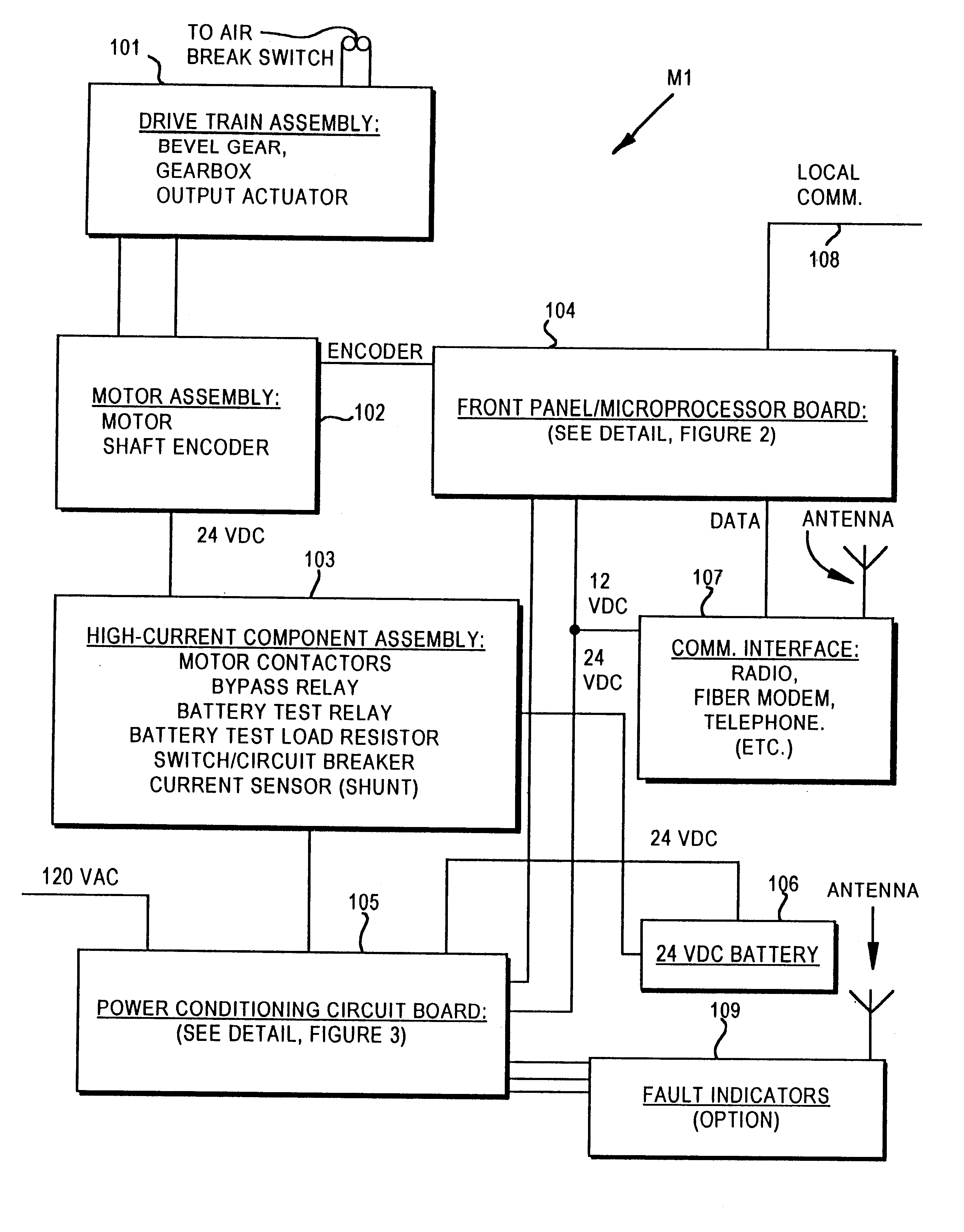
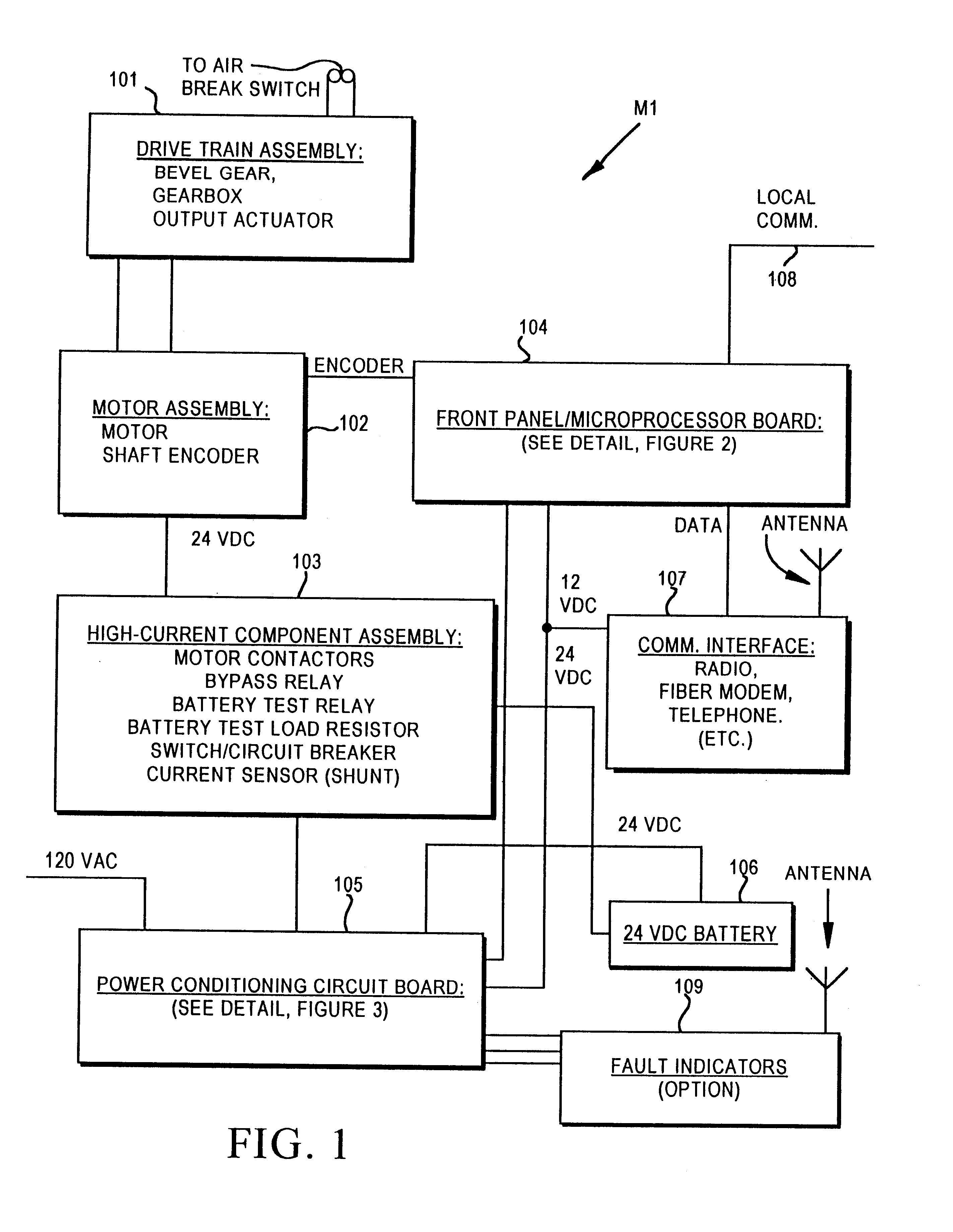
The M1 motor operator is fully under control of the microcontroller at all times. Before describing normal operation of the M1, however, it is important to understand some of the key interrupt and application-driven service functions performed in the background. These are shown in FIGS. 7a, b and 8. In these figures, the applicable interrupt is shown above the relevant logic underlined and in parentheses. The timer interrupt is state-driven. Each individual state is dictated by the value of a variable on entry to the interrupt, and the interrupt adjusts the state as necessary when transitions are required. The names of each state are shown as headings inside flowchart components, underlined and labeled as "States".

With regard to the operation sequence flowcharts and text, specific operation sequence names are all upper case characters. Mixed case underlined terms labeled "Indications" are significant software flags.

External Interrupt

Referring to FIG. 7a, the external int...


PUM


Abstract

A motor operator for an overhead power switch is disclosed including a microcontroller, a unique and powerful array of well-integrated sensors, a motor and drive developing substantial torque and speed and coupled to a switch actuator and responsive to the microcontroller, and a sophisticated program algorithm stored in memory at the actuator site for dynamically controlling, i.e., governing the various control modes as called for by changing conditions. The sensors include an encoder associated with the motor and drive that develops position information signals fed to the dynamic microcontroller to compute real time information including position, speed, and stopping distance used in conjunction with remote operate commands to open, close and monitor status of the switch in the various ways disclosed. Under the supervision of the microcontroller, a motor drive power switching circuit selectively applies a source of power, such as from an on site battery, to an electric motor to drive the switch toward open or closed position at different speeds, output force levels such as at different torques, and in continuous or incremental movements depending on conditions determined by the microcontroller in response to sensor inputs.

Description

1. Field of the InventionThe present invention relates to remotely controlled actuators for opening, closing and monitoring status of electrical power distribution switches of the type commonly used on overhead pole installations which close the contacts to carry high current--voltage and open to break the circuit with an ambient air gap separating the contacts.2. Background ArtThe most predominant method for routing electrical power to utility customers is through the use of single or three-phase electrical circuits carried on overhead power distribution lines. To allow these circuits to be disconnected, rerouted or otherwise reconfigured, air-break, single or gang-operated three-phase switches are commonly employed. These switches are typically mounted at the top of a wood, steel or concrete pole, and the operating actuator is typically carried down the pole on a wood, steel or fiberglass rod or shaft. The method for operating these switches is primarily manual, with a human opera...

Claims


Application Information

Patent Timeline
IPC IPC(8): H01H33/28H01H33/36H02H7/00H02H7/22
CPCH01H33/36H02H7/222H01H2003/266H01H2071/006
Inventor BERKOWITZ, DONALD S.BIK, WITOLDHAMMONS, JOHNHECKATHORN, JEFFISAACSON, STEPHEN F.KLUSMEYER, TERRY R.NELSON, WILLIAM CHRISTIAN TRACY
Owner S&C ELECTRIC
Why Eureka
Try Eureka