Parallel connected PTC elements

a technology of parallel connection and ptc elements, applied in the field of thermal protectors, can solve the problem of not always being able to enlarge the surface area of the ptc material layer

Inactive Publication Date: 2001-04-10
THERM O DISC
View PDF22 Cites 9 Cited by
  • Summary
  • Abstract
  • Description
  • Claims
  • Application Information

AI Technical Summary

Problems solved by technology

However, PTC devices must fit in confined spaces and it is not always possible to enlarge the surface area of the PTC material la

Method used


Image

  • Parallel connected PTC elements
  • Parallel connected PTC elements
  • Parallel connected PTC elements

Examples


Embodiment Construction

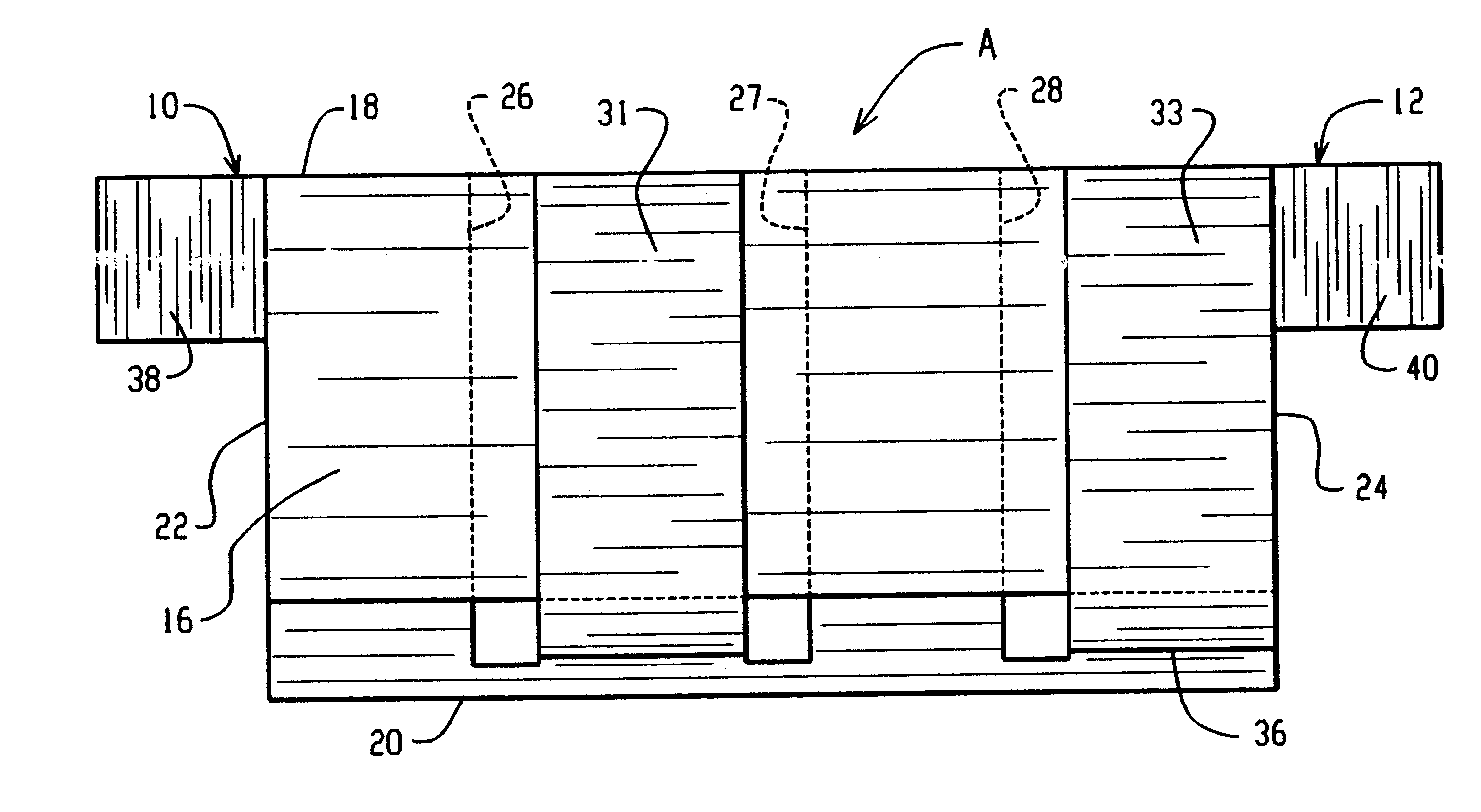
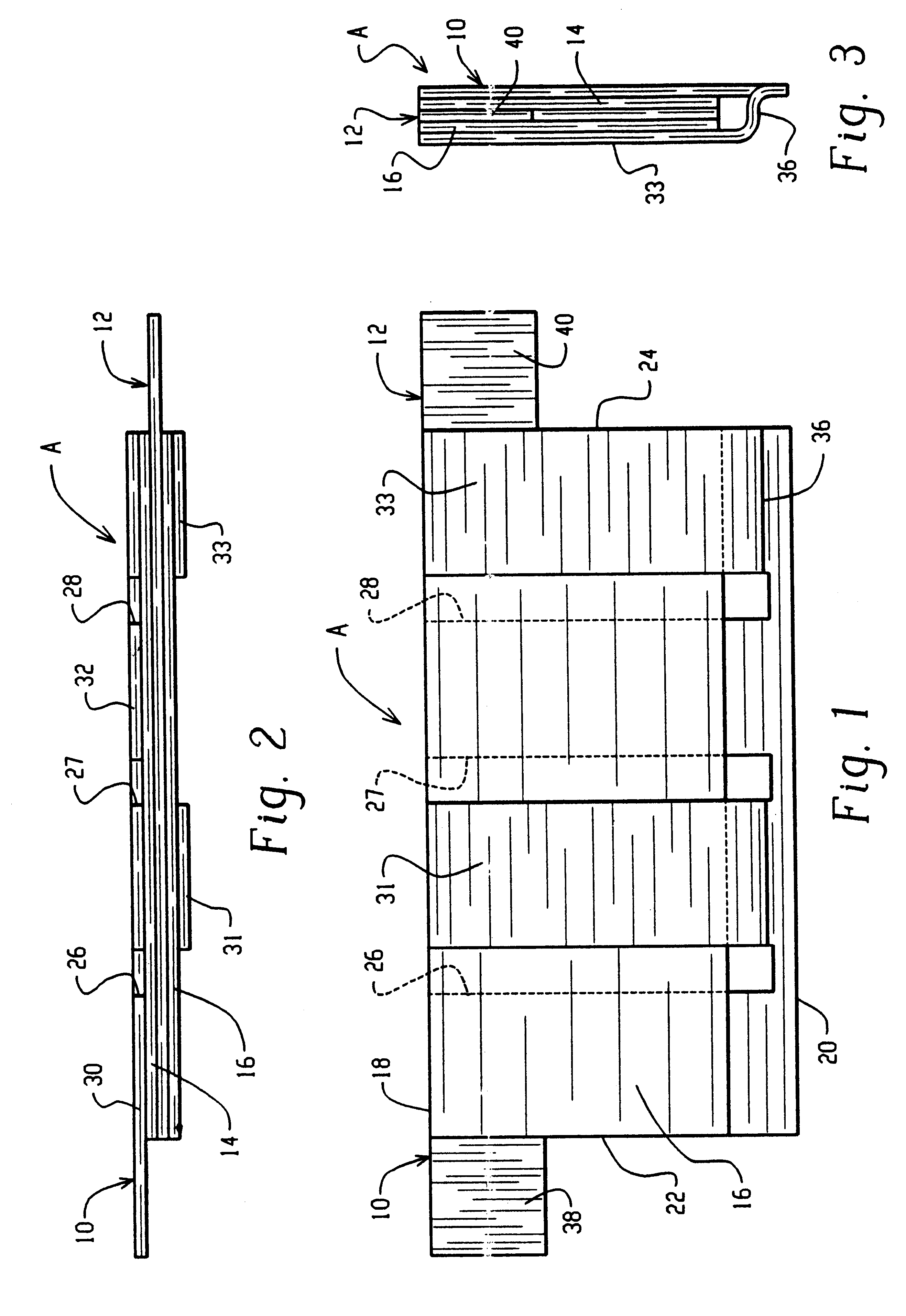
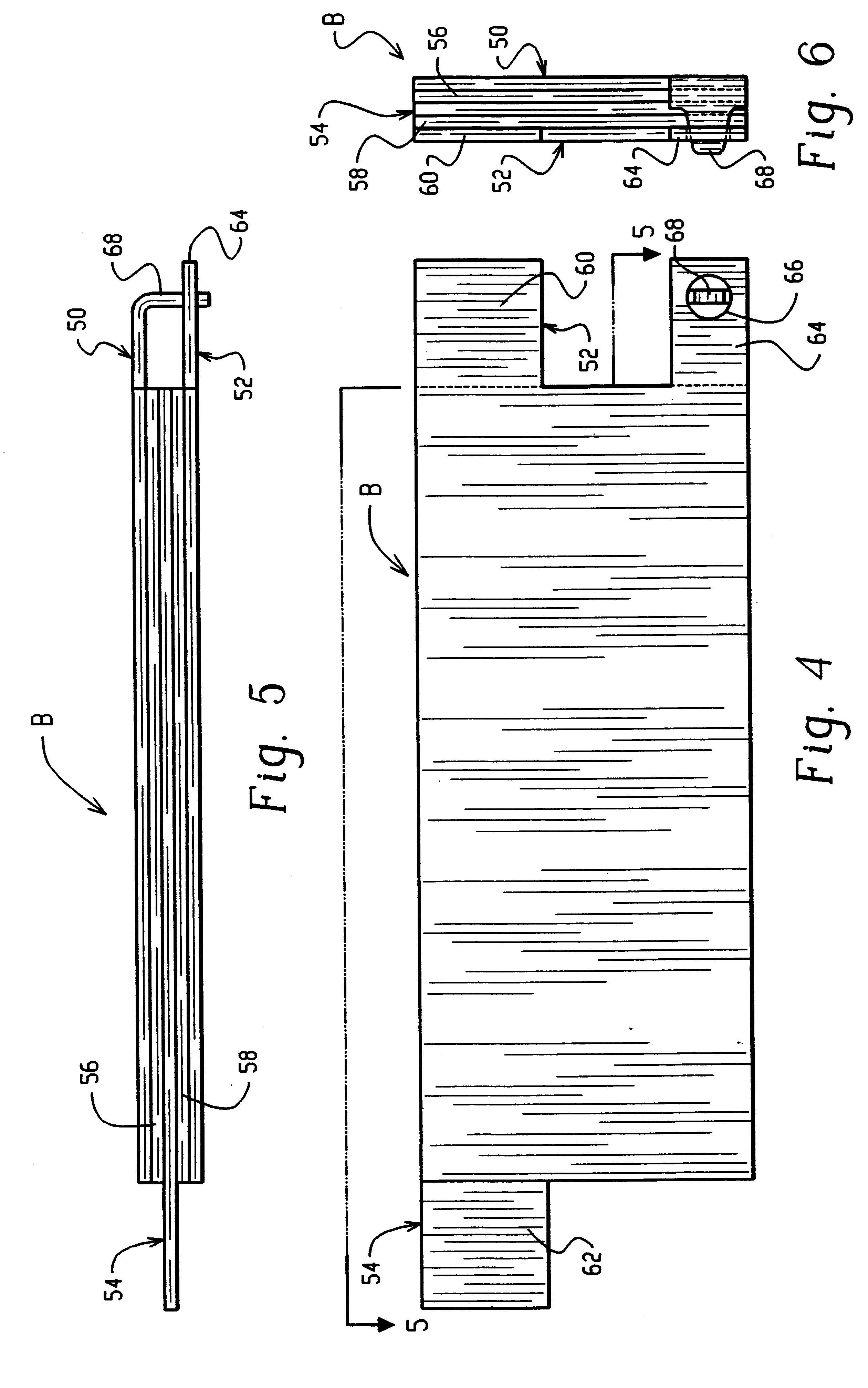
In all embodiments of the present application, it will be recognized that each PTC material layer is a polymeric compound containing carbon particles and having a positive temperature coefficient of resistance. The PTC material has a very low resistance at normal operating temperatures and an extremely high resistance above a predetermined switching temperature. The PTC material may reach its switching temperature by self-induced I.sup.2 R heating or by exposure to an elevated temperature in the surrounding environment. The PTC material automatically switches to its high resistance state at the switching temperature and effectively blocks current flow to an electrical apparatus that is protected by the PTC device. Metal foil electrodes (not shown) are bonded to both of the opposite faces of each PTC material layer and are coextensive in area with the PTC material layers. The metal plates are soldered to the foil electrodes. Thus, the PTC layers and the metal plates are bonded togeth...


PUM


Abstract

A plurality of PTC material layers and a plurality of metal plates are sandwiched together with one adjacent pair of metal plates connected in series through one layer of PTC material. The remaining PTC material layers are connected in parallel with the one layer by selectively interconnecting the other metal plates with the one adjacent pair of metal plates.

Description

BACKGROUND OF THE INVENTIONSThis application relates to the art of thermal protectors and, more particularly, to thermal protectors having electrical current limiting capabilities. The invention will be described with particular reference to thermal protectors that include a thin sheet of polymeric compound containing carbon particles and having a positive temperature coefficient of resistance. However, it will be appreciated that the invention has broader aspects and that it is possible to use other materials having a positive temperature coefficient of resistance.Thermal protectors that have a positive temperature coefficient of resistance are commonly referred to as PTC devices and the materials that provide such a resistance characteristic are commonly referred to as PTC materials. A thin layer of PTC material in a PTC device conducts electricity in a direction perpendicular to its thickness. Decreasing the resistance of such a PTC device during normal operation can be achieved ...

Claims


Application Information

Patent Timeline
IPC IPC(8): H01C7/18H01C1/14H04L7/04H01C7/02G11B20/18G11B27/30H04L1/00H04N7/50H04N7/66
CPCG11B27/3027H01C1/1406H01C7/18H04L1/0041H04L1/0045H04L1/0083H04L7/041H04L7/048H04N19/61H04N19/00G11B20/1813H04L2001/0098H04N19/70
Inventor WEST, JEFFREY A.
Owner THERM O DISC
Why Eureka
Try Eureka