
Visual calibration

a color printer and calibration apparatus technology, applied in the field of color printer calibration, can solve the problems of high labor intensity, drift in color response, and complex printing technologies, including electrophotographic and ink jet technology, and achieve the effect of reducing labor intensity and reducing labor intensity

Inactive Publication Date: 2001-04-10
ELECTRONICS FOR IMAGING
View PDF36 Cites 97 Cited by
  • Summary
  • Abstract
  • Description
  • Claims
  • Application Information

AI Technical Summary

Problems solved by technology

Many printing technologies, including electrophotographic and ink jet technology, are complex and, due to many different physical and environmental factors, may drift in their color response, i.e. the amount of color toner or ink that is printed on a paper.
A major disadvantage of this method is that the process of specifying the aim points requires a highly trained operator.
Again, a major disadvantage is this process requires a user with a significant amount of training.
This method has some significant limitations.
For example, this method does not allow a way to accurately display or print computer rendered images, i.e. images that do not originate as scanned images but rather are originally generated by the computer.
The disclosed technique works in conjunction with specific engine adjustments and controls (developer charge control, as an example) but does not generate digital transfer curves for printer control and therefore does not provide a uniform interface across printer models and technologies.
Dundas does not minimize the iterations needed and does not maximize the accuracy of the calibration in highlights and gray balance.
Instruments cost money.
The user may want good color quality, but may not be ready to purchase a densitometer, that is more expensive than many low end printers, preexisting reference targets.
Instruments can deliver unreliable results.
Some low-end printers are incapable of producing the same color across the page.
Papers can be unreliable.
Very often, lower quality papers are irregular in thickness and coating.
Also, an operator may not notice a certain spot on a specific sheet of paper where a sample is measured.
No calibration method is known that allows for visual calibration to arbitrary color response goals or different settings.

Method used


Image

  • Visual calibration

Examples


Embodiment Construction

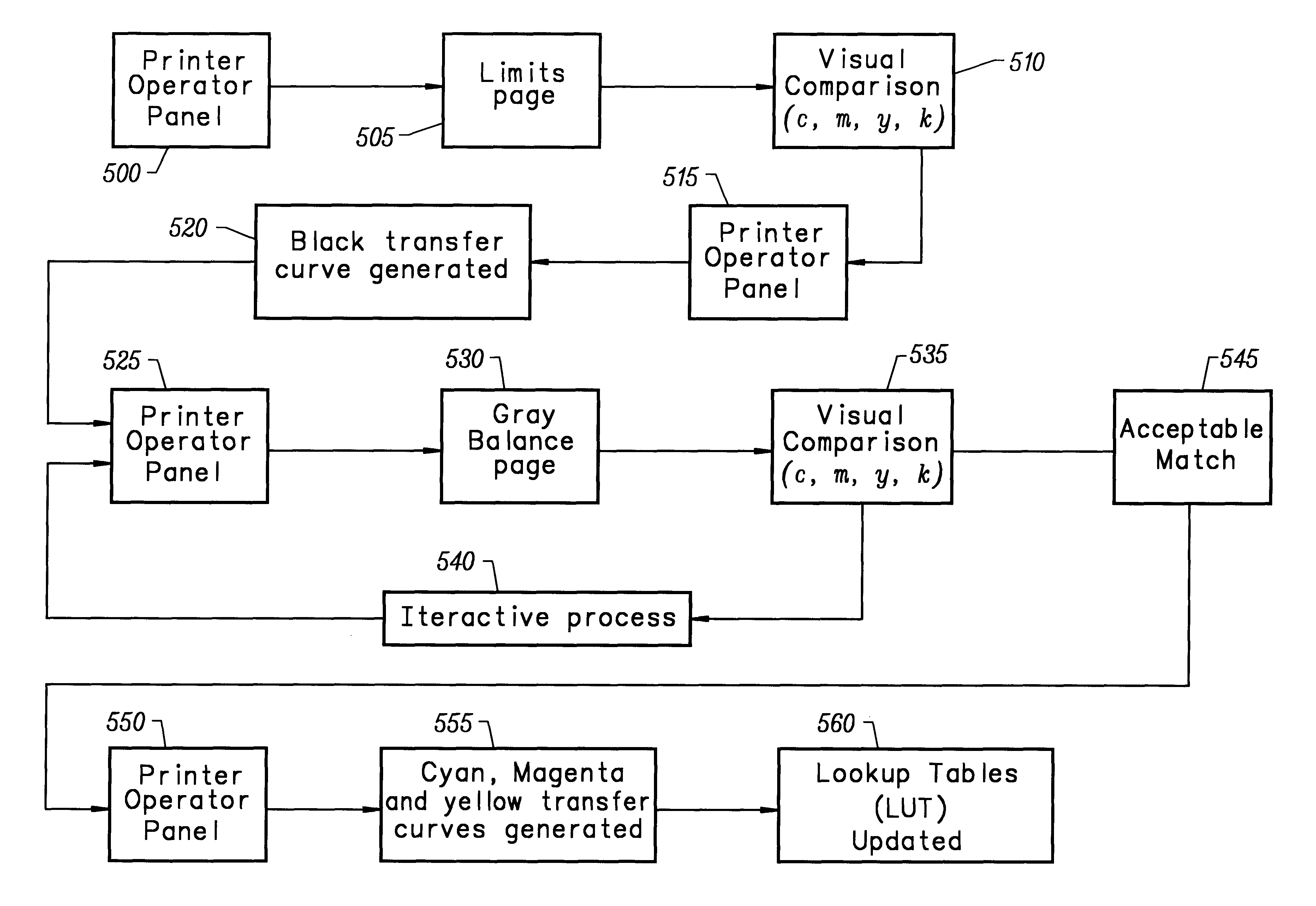
The invention provides a calibration apparatus and method that allows a user to calibrate a printer without having prior training and without the use of expensive measuring instruments. The invention is also compatible with densitometer calibration. The invention does not require special preexisting reference targets, which can be costly and difficult to manufacture, and which can fade over time. The invention allows for calibration to arbitrary color response goals such as, for example, goals from a print device or presses that use DIC ink or SWOP inks. The goals could be generated from an ICC (International Color Consortium) profile. The preferred embodiment of the invention compensates for the drift in color response of printers by making visual comparisons of prints made by a printer to be calibrated. The process is iterative and therefore can be made as good as desired in the sense of coarse or fine iterations. The end result of the calibration process is a set of four curves o...


PUM


Abstract

A calibration apparatus and method for a color printer that allows a user to calibrate a printer without the use of expensive measuring instruments and prior user training is provided. The calibration process prints out two target layouts. On the first target the user selects the primary inks start and end points (highlights and shadows), and the black ink only input value that generates a 30% gray. The primary inks are the device-dependent colorants, cyan, magenta and yellow. The second target compares the 30% black ink with grays made of a combination of cyan, magenta and yellow inks. The user selects the best match in an iterative process. Using this data, calculations are made of the corrections to the original input signal values for the printer. A look up table is updated with corrected input values to compensate for the printer deviation from its standard behavior.

Description

1. Field of the InventionThe invention relates to the calibration of a color printer. More particularly, the invention relates to a calibration apparatus and method for a color printer, where the calibration is performed in such a way that prior training and expensive equipment are not required.2. Description of Prior ArtMany printing technologies, including electrophotographic and ink jet technology, are complex and, due to many different physical and environmental factors, may drift in their color response, i.e. the amount of color toner or ink that is printed on a paper. That is, a particular combination of input colorants to the printer, cyan, magenta, yellow, and black, or (c,m,y k), results in a different color response when printed to one printer at different times or when printed to different printers of the same model. Preferably, the color response should be steady through time and consistent between different devices. Prior art systems attempt to compensate for the differ...

Claims


Application Information

Patent Timeline
IPC IPC(8): H04N1/60
CPCH04N1/6033
Inventor MICHEL, PAULSAMADANI, RAMIN
Owner ELECTRONICS FOR IMAGING
Learn More