
Method and system for efficient control of the execution of actions in an object oriented program

a technology of object oriented programs and methods, applied in the field of data processing systems, can solve problems such as limiting the ability of compound objects to be constructed and customized

Inactive Publication Date: 2001-04-10
IBM CORP
View PDF12 Cites 28 Cited by
  • Summary
  • Abstract
  • Description
  • Claims
  • Application Information

AI Technical Summary

Benefits of technology

U.S. Pat. No. 5,050,074 describes a system for facilitating coordination of activities by a plurality of actors with an object data base and state / action identification. The system according to the patent includes a plurality of objects each associated with a constituent, with each object including state information defining a state and constituent information containing information relating to a constituent. The system further includes tables to identify processing actions in connection with the various states of each object, state transitions for each object in connection with each action defined by the action definition table, and actors associated with each constituent. The system initially determines, in response to constituent information from an actor and the object access definition table, the association of the actor with respect to a constituent and selectively processes the object associated with the constituent as defined by the action definition table and modifies the state of the object as defined by the state transition definition table. In the system according to the present invention, the actions related to the various states of each object are kept as part of the state that belongs to that object. The action information is not stored in a global action definition table as in the prior art. This improves the overall response time of the system. The system described in U.S. Pat. No. 5,050,074 also includes a table to keep state transitions for each objects actions. In other words, the actions are limited to primitive state transitions. In the system according to the present invention, the actions can be defined through method calls, scripts, procedure calls, and action slot executions.
There are two primary forms of actions implied with direct object manipulation; the first is a direct repositioning of the object to another location on the screen, and the second is an action-object type of direct object manipulation where the object undergoing direct object manipulation is dragged over another object, the target object, initiating an action. Direct object manipulation provides a set of messages and functions to accomplish both forms of direct object manipulation and is used in the IBM OS / 2 Presentation Manager program. As described above, there are two primary forms of actions implied with direct manipulations; direct repositioning, and a target object initiating an object. These are simple cases of actions and they are tailored to be used for direct manipulation. The system according to the present invention is not limited to just "a direct manipulation", it is the general purpose system that can be used to create compound objects with complex interactions. Furthermore, the action orientation described in the Technical Disclosure Bulletin article is not object oriented in the sense that the action information is kept as state variables in the source or target objects. The action information is not represented as a first class object. In the system according to the present invention, action objects are first class objects thus providing the advantages like extendibility and modularity.

Problems solved by technology

Other prior art application frameworks employing object oriented programming systems employ only one type of action object which limits their ability to construct and customize compound objects.

Method used


Image

  • Method and system for efficient control of the execution of actions in an object oriented program
  • Method and system for efficient control of the execution of actions in an object oriented program
  • Method and system for efficient control of the execution of actions in an object oriented program

Examples


Embodiment Construction

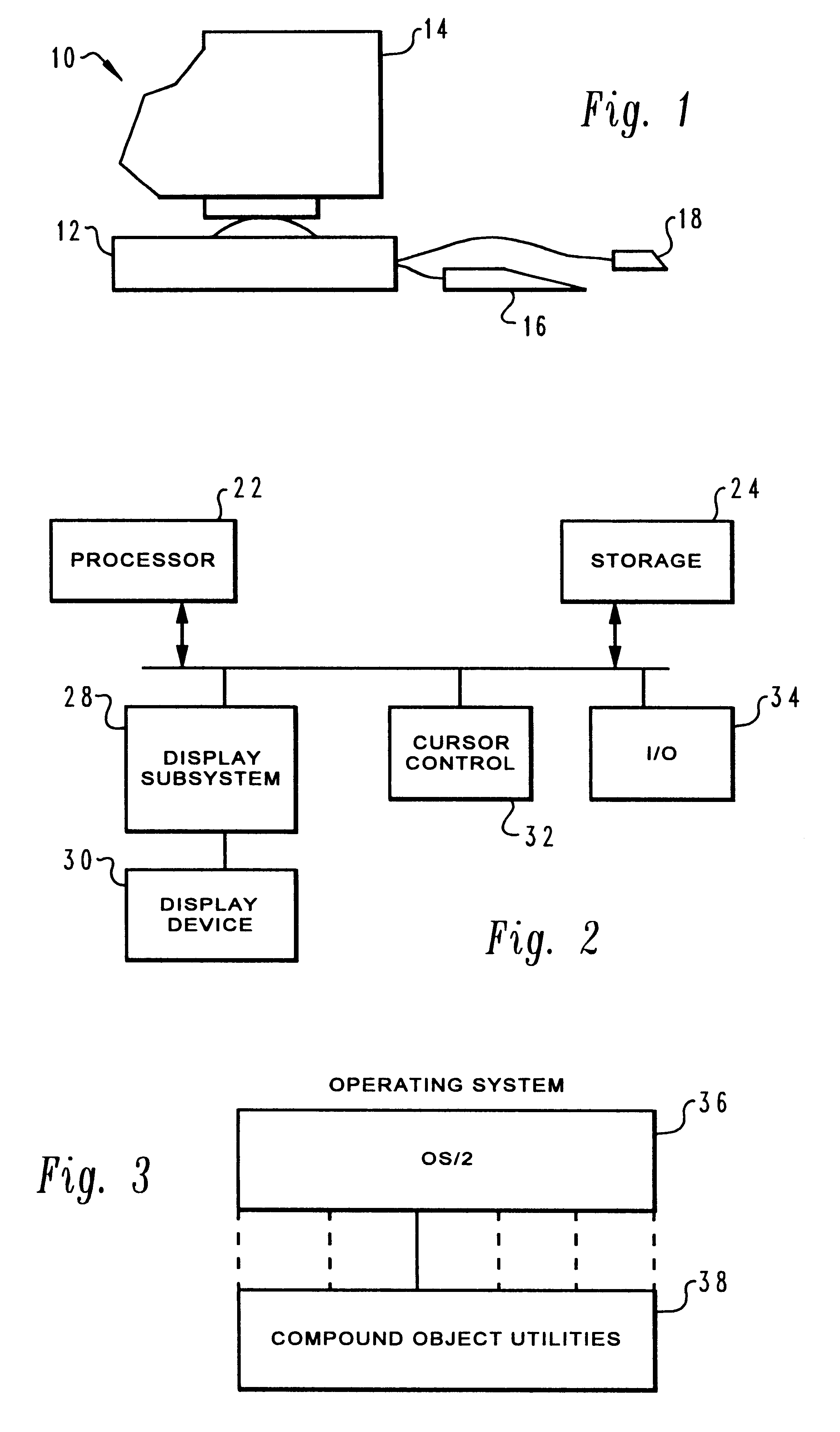
Referring now to FIGS. 1 and 2, a data processing system in accordance with the present invention will be generally described. Data Processing System 10 may be for example a stand-alone graphics workstation having a system unit 12, a color graphics monitor 14, a keyboard 16, and a mouse or other cursor control device 18. Modern graphics workstations are very powerful data processing systems which combine state of the art processing capability with large internal main memories coupled to peripheral storage systems such as magnetic disk drives or optical compact disks to provide the large amount of readily available storage required for graphics applications.

Data Processing System 10 includes processor 22, storage 24, bus 26, display subsystem 28 which drives a display device 30, cursor control logic 32 and input / output channel 34.

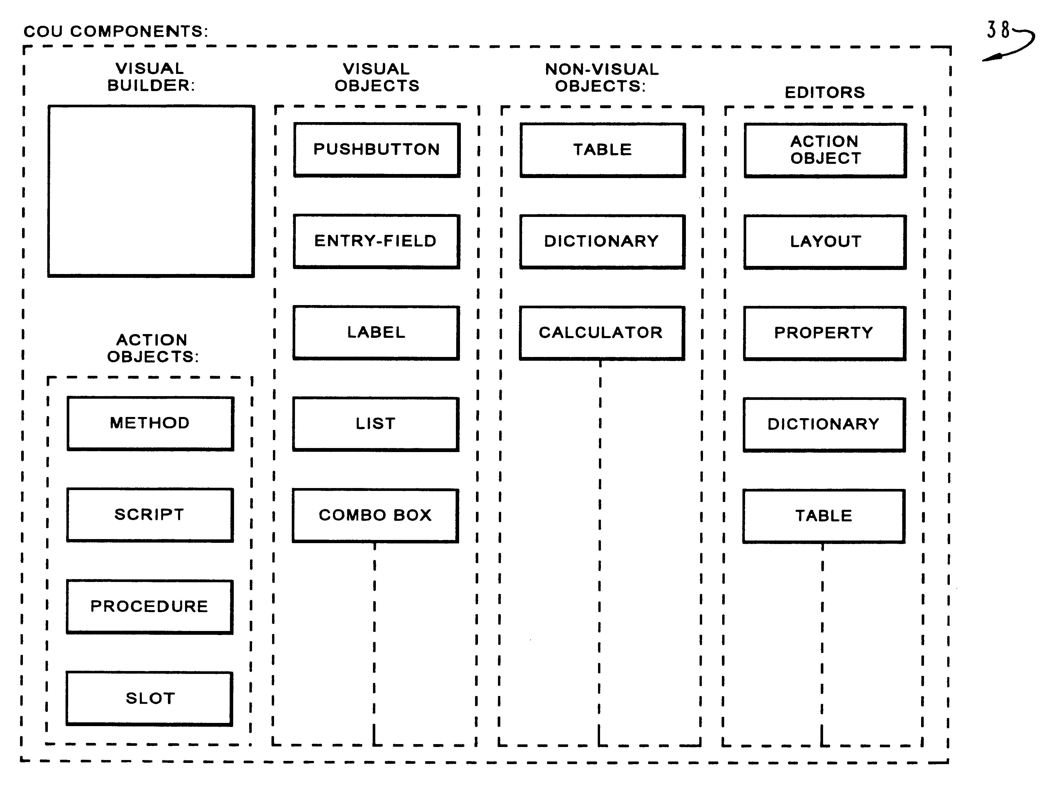
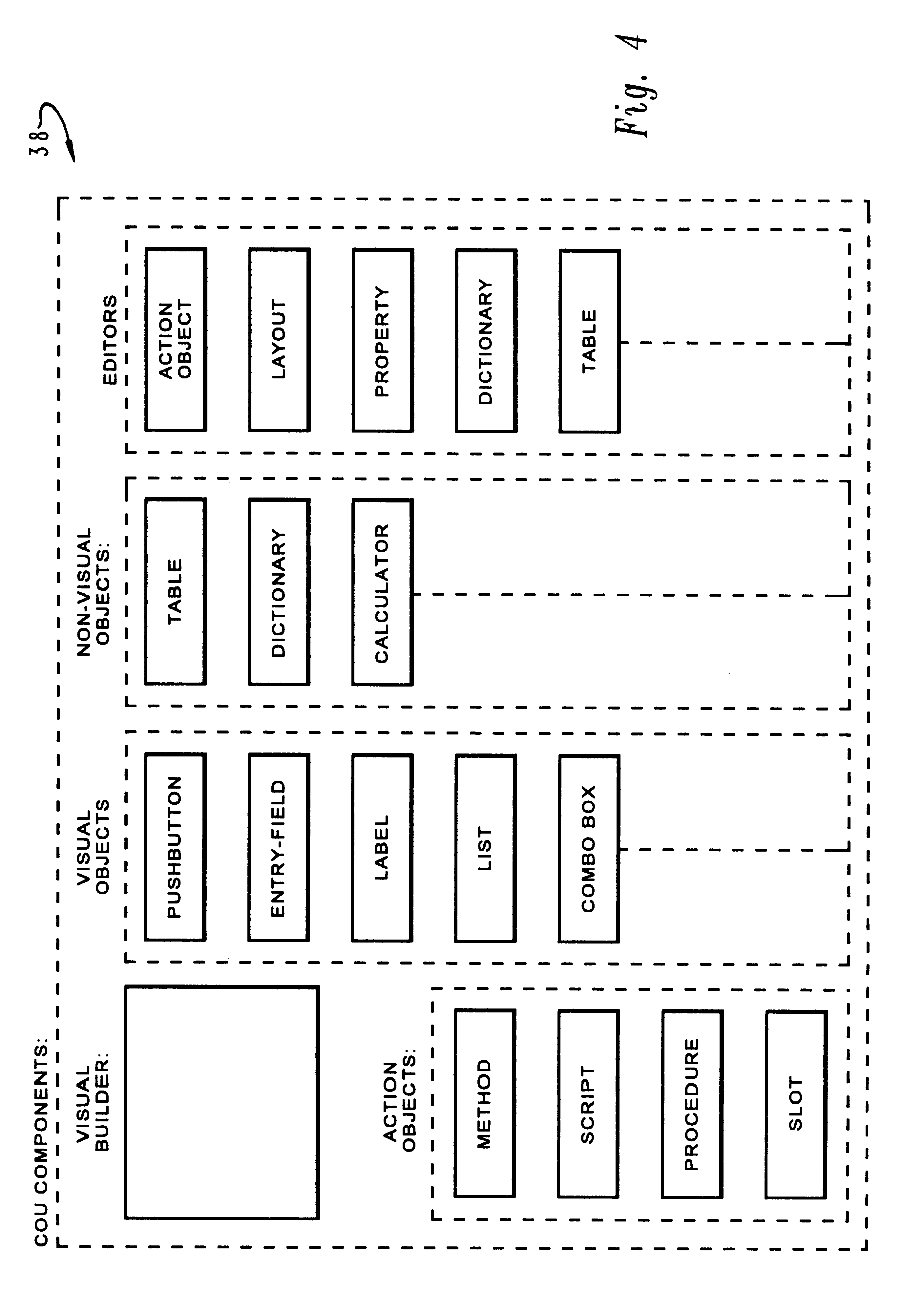
Referring now to FIG. 3, the control system will be generally described.

The data processing system described above with reference to FIGS. 1 and 2 may be co...


PUM


Abstract

A method and system for efficiently controlling the execution of actions in an object oriented program. An observable object is defined which responds to a predetermined number of abstract events, each abstract event corresponding to an action slot container object which is associated with the observable object. New abstract events may be defined at execution and a corresponding new action slot container object associated with the observable object at that time. One or more action objects which each specify a unit of behavior are then defined and placed within the action slot container objects such that the occurrence of a corresponding abstract event may initiate the occurrence of multiple units of behavior. Separate subclasses of action objects are also defined, each subclass specifying a manner in which the specified unit of behavior will be implemented. In this manner, methods, scripts, procedures, and other abstract events may be initiated in response to an execution of an action object and a determination of the subclass to which that action object belongs.

Description

1. Technical FieldThe present invention relates to data processing systems, and more particularly to data processing systems employing object oriented programming to construct programs for execution on a data processing system.2. Description of the Related ArtObject oriented programming systems provide means for creation and reuse of objects for the purpose of program generation, database management, graphical user interface generation and similar applications. To make most efficient use of object oriented programming, a variety of tools or utilities are required to overcome deficiencies in programming language and operating systems. More particularly, in the design and implementation of application program frameworks, there is a need to create object libraries and to extend well-known programming languages such as the C language to have object oriented capabilities. Further, applications should be designed and implemented so that they may be operating system independent and be able...

Claims


Application Information

Patent Timeline
Patent Type & Authority Patents(United States)
IPC IPC(8): G06F9/44
CPCG06F8/24
Inventor CONNER, MICHAEL HADENCOSKUN, NURCAN
Owner IBM CORP
Learn More