Electronic flash device of a separate excitation oscillating type

a flash device and electric motor technology, applied in the field of electric motor flash devices and cameras, can solve the problems of longer charging time and inability to put the charging circuit of the separate excitation flyback type to practical us

Inactive Publication Date: 2001-04-17
KONICA CORP
View PDF4 Cites 26 Cited by
  • Summary
  • Abstract
  • Description
  • Claims
  • Application Information

AI Technical Summary

Benefits of technology

As a result, it is possible to conduct appropriate control even for the battery whose electromotive force is weakened, by referring to battery voltage of the battery used for charging.
It is therefore possible to prevent generation of the so-called "idle time" which contributes neither to charging of the main capacitor nor to energy accumulation in the flyback transformer, in accordance not only with charging time but also with variation of battery voltage.

Problems solved by technology

Therefore, the time for the oscillation transistor to be turned off needs to be set in synchronization with the timing wherein charging voltage of the main capacitor is low and the time for flyback pulses to be generated is long, resulting in generation of the so-called "idle time" which contributes neither to accumulation of energy of a transformer nor to charging on the main capacitor caused by generation of flyback pulses, on the point of completion of charging.
For this reason, there has been disadvantage that the charging time is made longer.
Therefore, the charging circuit of the separate excitation flyback type has not been put to practical use.

Method used


Image

  • Electronic flash device of a separate excitation oscillating type
  • Electronic flash device of a separate excitation oscillating type
  • Electronic flash device of a separate excitation oscillating type

Examples


first embodiment

(First embodiment)

An embodiment of the invention will be explained in detail as follows.

(Structure of an electronic flash device)

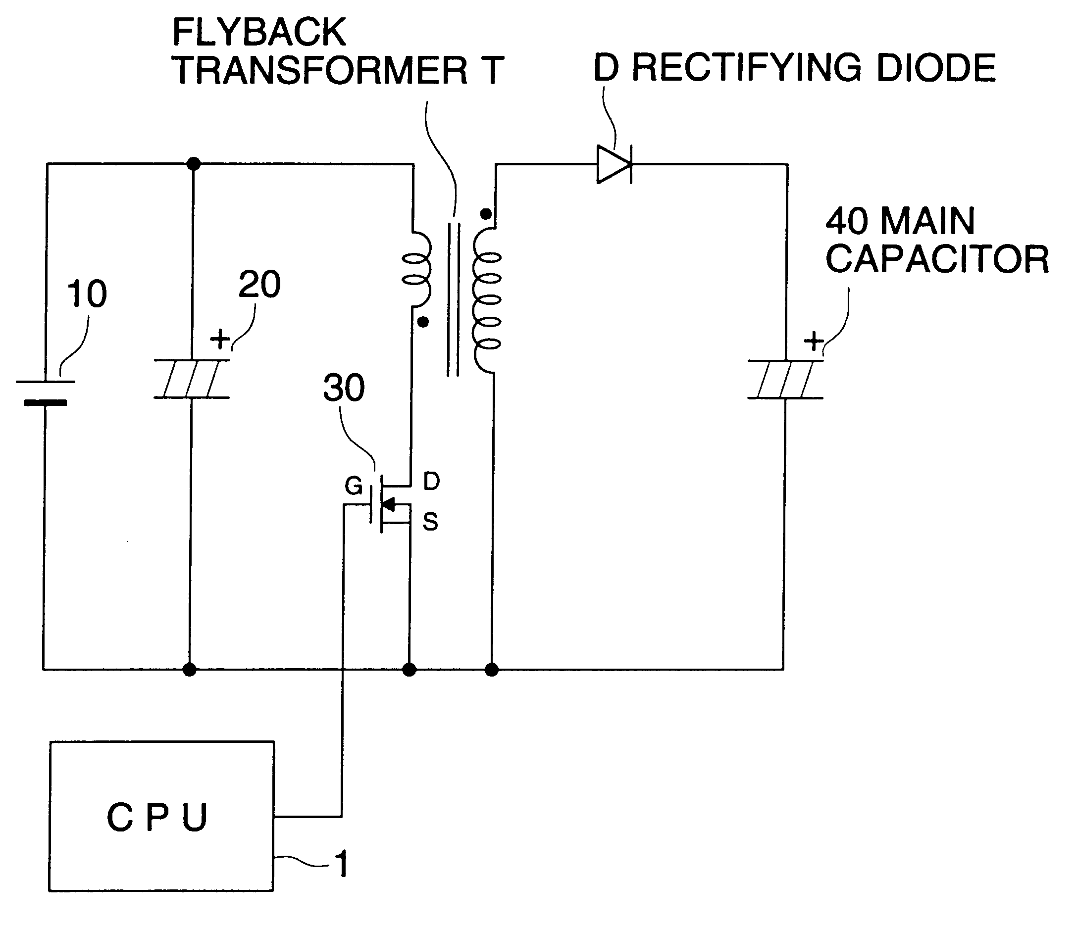
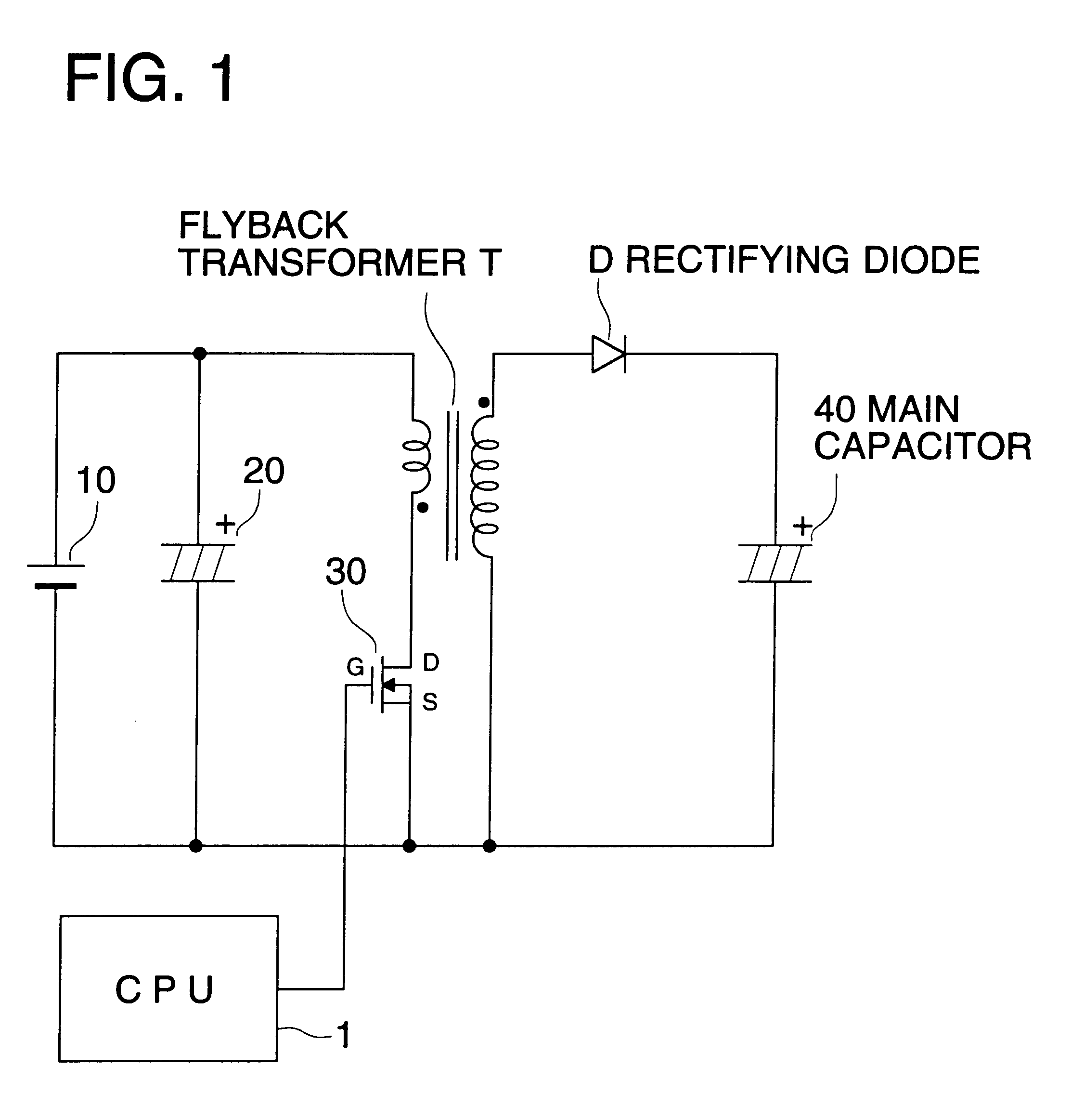
First, the schematic structure of an electronic flash device used in the present embodiment will be explained as follows, referring to FIG. 1. FIG. 1 represents a functional block diagram showing the general electrical structure of an electronic flash device in an embodiment of the invention.

The electronic flash device in the present embodiment shown in FIG. 1 is an electronic flash device of a separate excitation flyback type wherein a circuit of a separate excitation oscillation type and a circuit of a flyback type are combined to be used.

A step up circuit of a separate excitation flyback type is provided with a characteristic that consumption current can be controlled, because behavior of the current flowing through the primary coil is constant independently of charging voltage, due to operations of a flyback type wherein an electric current is caused t...

second embodiment

(Second embodiment)

Next, another embodiment will be explained as follows, referring to FIG. 17. Now, the only points differing from the first embodiment will be explained. The numeral 50 represents a pulse detecting section which detects flyback pulses on one end of the secondary coil of flyback transformer T, and it is composed of a diode and a voltage dividing resistance, and results of detection of flyback pulses are supplied to CPU 1.

FIG. 18 shows the circuit structure of the similar electronic flash device wherein pulse detecting section 50 is detecting flyback pulses on one end of the primary coil of flyback transformer T.

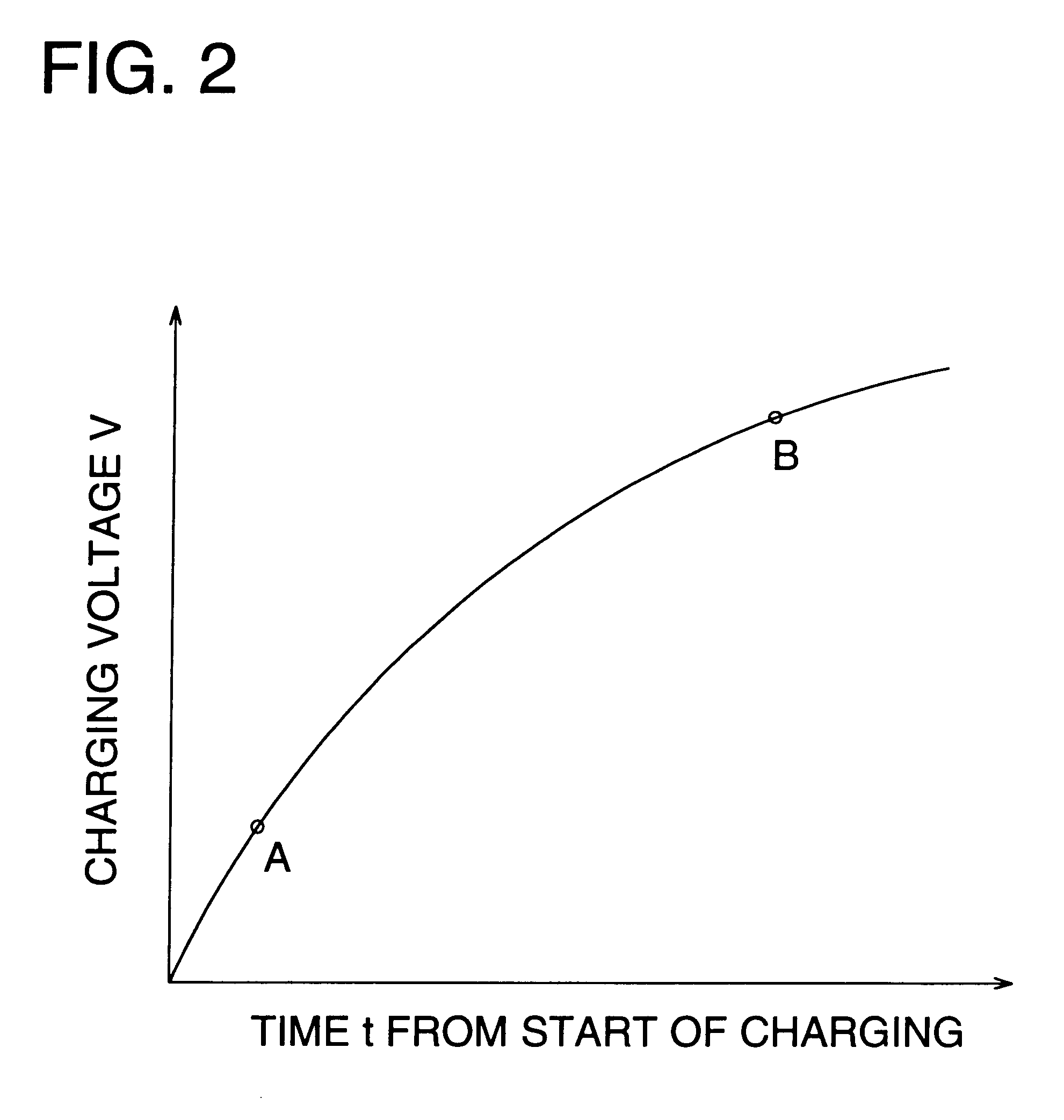
Operations of the electronic flash device of the present embodiment are the same as those explained with reference to FIG. 2 and FIGS. 3(a)-3(f) in the first embodiment, and when charging advances and voltage in the main capacitor 40 becomes higher, a period contributing to no charging is increased. Namely, a period following the generation of flyback pulses ...

example

When it is assumed that the duty ratio of 58% is taken after the setting of ON:10 .mu.s and OFF:8 .mu.s (duty ratio: 55.6%) when changing the time as charging voltage rises, the setting of ON:11 .mu.s and OFF:8 .mu.s (duty ratio: 57.9%) with the changed ON time is closer to the desired setting than the setting of ON:10 .mu.s and OFF:7 .mu.s (duty ratio: 58.8%).

It is possible to conduct rapid charging by preventing generation of idle time and by controlling so that the number of flyback pulses generated within a specified period may be increased or they may be made greater. In this case, consumption current grows as charging advances, but the oscillation transistor is turned on after extinction of the flyback pulses. Therefore, it is possible to conduct charging while keeping high conversion efficiency, without having the control that the oscillation transistor is turned on when charging current is flowing.

FIG. 12 shows the circuit structure of an electronic flash device, and it show...


PUM


Abstract

An electronic flash charger having an electronic flash charging circuit of a separate excitation oscillating. The charger includes: a flyback transformer, having at least a primary coil and a secondly coil; a switching element for turning on or off electric power, to be supplied to the primary coil, based on control signals supplied to a control input terminal; a rectifying diode for rectifying a flyback pulse generated on the secondly coil when the switching element is changed from ON state, that the electric power is turned on, to OFF state, that the electric power is turned off; a main capacitor for charging a current rectified by the rectifying diode; and an oscillation controller for generating control signals for changing at least one of time spans of ON state and OFF state of the switching element in accordance with a period from generation to extinction of the flyback pulse generated on the secondly coil, and for supplying the control signals to the control input terminal of the switching element.

Description

The present invention relates to an electronic flash device which controls an illuminating unit for a camera (electronic flash) in the course of photographing.When a type of the electronic flash device is classified roughly, it includes the following.Classification by an oscillating typeSelf-excitation oscillating type: A type wherein a circuit which oscillates by it self is structured in a charging circuit.Separate excitation oscillating type: A type wherein oscillation control signals are given to an oscillating element from the outside.Classification by a type of voltage step upForward Type:A type wherein voltage impressed on a primary coil of a transformer is stepped up in accordance with the turns ratio of the primary coil to a secondary coil, and is outputted on the secondary coil.Flyback Type:A type wherein backward voltage which is generated when an electric current that is running through the primary coil is interrupted, is generated on the secondary coil.Therefore, those w...

Claims


Application Information

Patent Timeline
Patent Type & Authority Patents(United States)
IPC IPC(8): G03B15/05
CPCG03B15/05G03B2215/05
Inventor AOKI, TOSHIYUKIYASUI, TERUHIKO
Owner KONICA CORP
Why Eureka
Try Eureka