Exhaust emission control system for internal combustion engine

a technology for exhaust emission control and internal combustion engines, which is applied in the direction of electric control, machines/engines, instruments, etc., can solve the problems of inability of either side to achieve accurate detection of a/f ratio by the use of the downstream side, and the detection value of the a/f ratio varies,

Inactive Publication Date: 2001-04-24
NISSAN MOTOR CO LTD
View PDF17 Cites 19 Cited by
  • Summary
  • Abstract
  • Description
  • Claims
  • Application Information

AI Technical Summary

Problems solved by technology

The exhaust gas enters the measurement gap 24 by diffusion, so there is a problem that depending upon the different diffusion speeds, the above described gaseous elements differ in the time necessary for them to arrive the detecting portion (i.e., electrode surface), from each other.
However, in case the wide-range A / F ratio sensor is disposed downstream of the catalytic converter, the ratio between hydrogen and carbon monoxide contained in the exhaust gas is varied by the so-called water gas reaction, thus causing a problem that the detected value of the A / F ratio varies under the influence of the water gas reaction.
Thus, either of two cannot realize accurate detection of the A / F ratio by the use of the downstream side A / F ratio sensor, particularly on the rich side of the stoichianetry.
A problem of the prior art exhaust emission control system having a wide-range A / F ratio sensor downstream of a catalytic converter is the catalytic converter causes a so-called water gas reaction to vary that the ratio between hydrogen and monoxide contained in the exhaust gas, so the A / F ratio sensor cannot attain accurate detection of the A / F ratio due to the influence of the water gas reaction.
Various efforts have been made with a view to overcoming the above described problems but there has not been proposed any exhaust emission control system of the above described type whose A / F ratio sensor can attain an accurate detection of the A / F ratio particularly when the mixture is rich (excess fuel in it).

Method used


Image

  • Exhaust emission control system for internal combustion engine
  • Exhaust emission control system for internal combustion engine
  • Exhaust emission control system for internal combustion engine

Examples


first embodiment

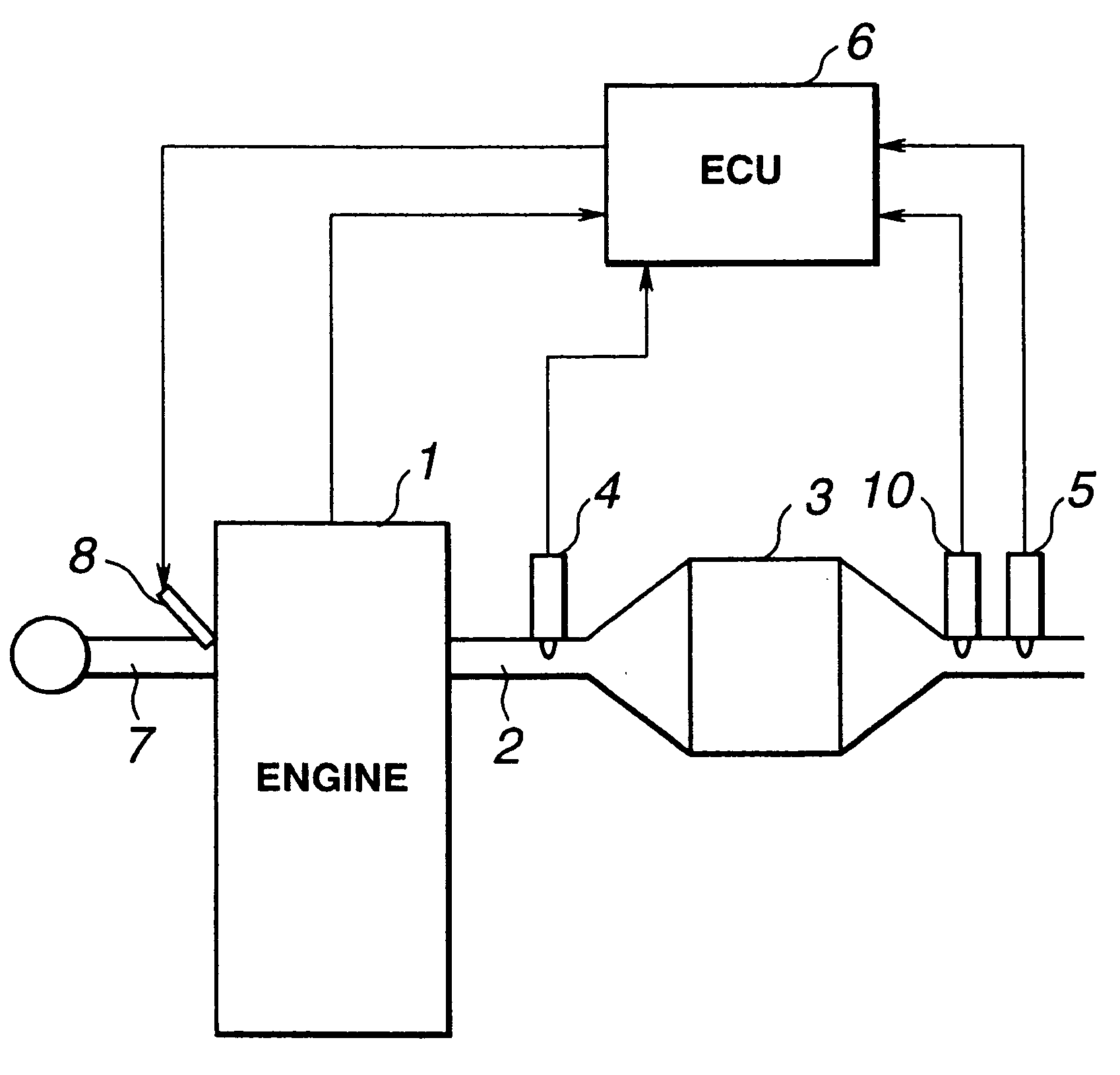
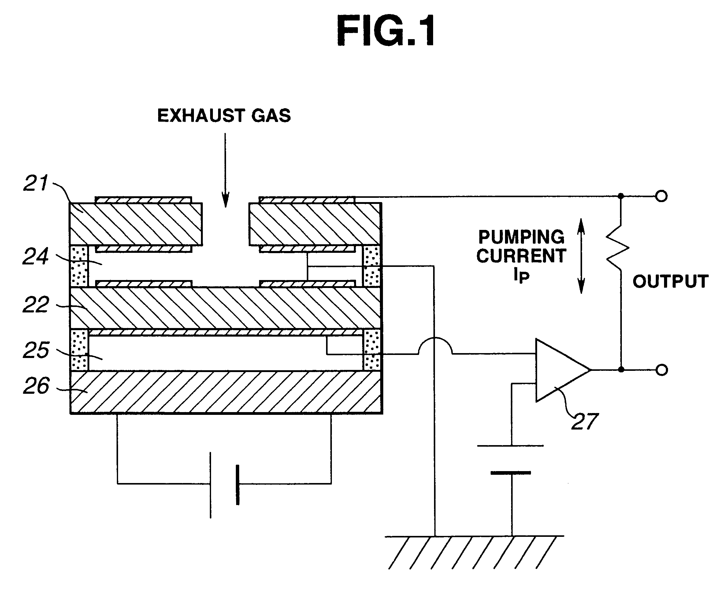
Referring first to FIG. 5, an exhaust emission control system according to the present invention includes a catalytic converter 3 having a three-way catalyst and disposed in an exhaust pipe or passage 2 of an internal combustion engine 1. Also disposed in the exhaust passage 2 at locations upstream and downstream of the catalytic converter 3 are a first A / F ratio sensor 4 and a second A / F ratio sensor 5 for detecting the A / F ratio, respectively. The both A / F ratio sensors 4 and 5 are the aforementioned wide-range A / F ratio sensors and are adapted to detect the A / F ratios which are represented by pumping current. The detection signals of the A / F ratio sensors 4 and 5 are inputted to an engine control unit (ECU) 6. To an intake pipe or passage 7 of the internal combustion engine 1 is attached a fuel injector 8 which is adapted to inject fuel in response to an injection signal from the ECU 6. Though the fuel injection quantity is basically controlled in accordance with an operating con...

second embodiment

FIG. 20 shows a second embodiment in which a catalyst temperature sensor 9 is provided to the catalytic converter 3 for detecting the catalyst temperature. FIG. 9 shows a flowchart for obtaining the catalyst deterioration degree R on the basis of the history of catalyst temperature which is obtained by the catalyst temperature sensor 9 provided as above. By the catalyst temperature sensor 9, the catalyst temperature Tc is detected directly (step S20). Then, the catalyst deterioration degree Ra corresponding to the catalyst temperature Tc is obtained by using a map (step S21). The catalyst deterioration degrees Ra are added up in sequence to obtain the age-based catalyst deterioration degree R (step S22) and stored in the memory (step S23). In the meantime, in case the catalyst deterioration sensor 9 is provided in this manner, the above described basic hydrogen correction quantity Sa can be determined on the basis of the catalyst temperature Tc.

third embodiment

FIG. 21 shows a third embodiment in which a hydrogen sensor 10 which is directly reactive to a hydrogen concentration is used for measuring the degree of water gas reaction. The hydrogen sensor 10 includes, for example, a catalytic layer selectively reactive to hydrogen and a catalytic layer not reactive to hydrogen and is operative to detect the hydrogen concentration on the basis of the difference in temperature between the two layers.

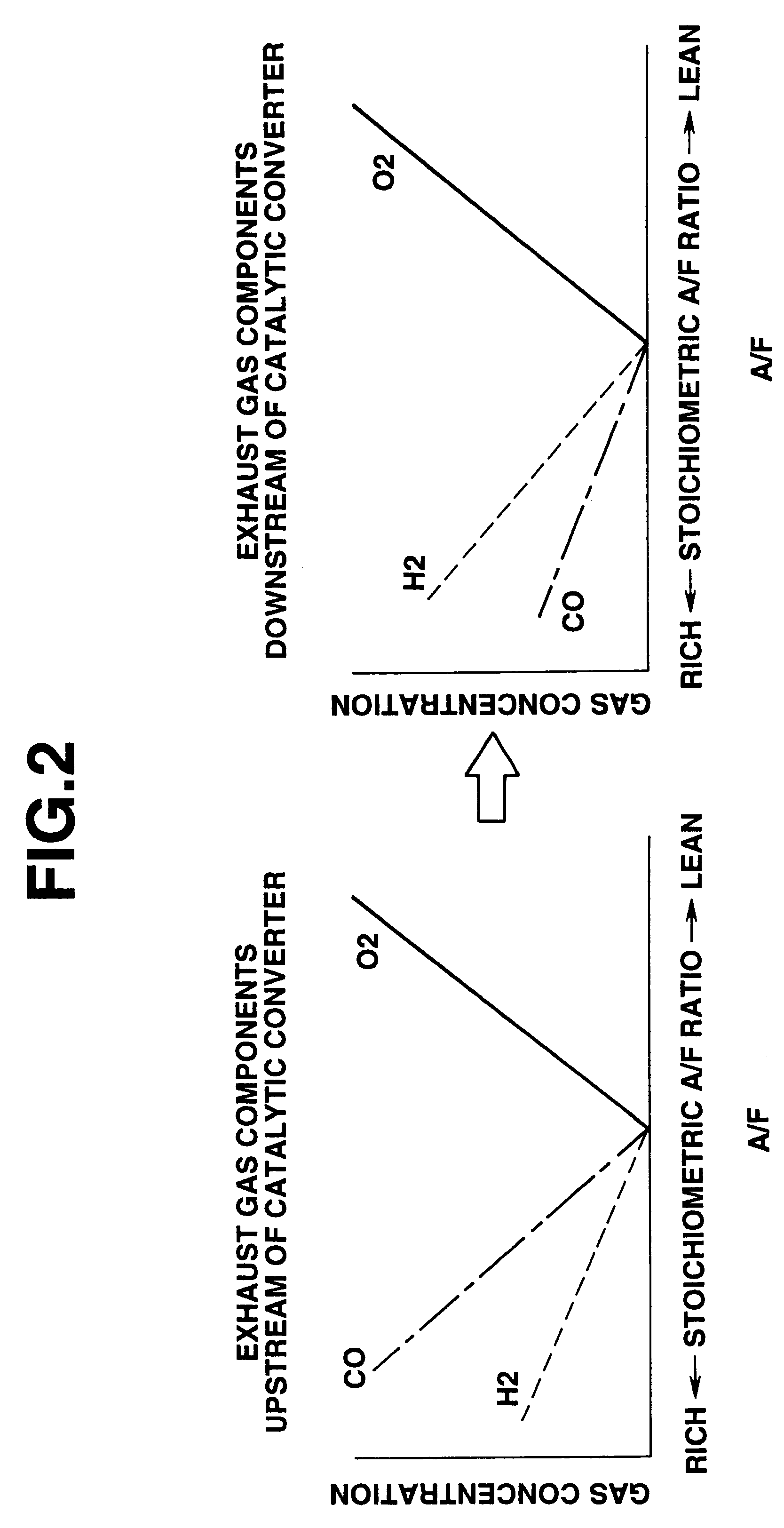
The flowchart in FIG. 10 shows a subroutine of the step S5 for the third embodiment, which will be described hereinlater. At step S24, the pumping current Ipb of the second A / F ratio sensor 5 is read. At step S25, it is judged on the basis of the pumping current Ipb whether the A / F ratio is rich, i.e., the pumping current is negative or not. As described above, in case the A / F ratio is lean, there is scarcely an influence of water gas reaction to the pumping current Ipb. Thus, no correction is made to the pumping current Ipb, and the program proceeds...


PUM

PropertyMeasurementUnit
temperatureaaaaaaaaaa
catalytic temperatureaaaaaaaaaa
concentrationaaaaaaaaaa

Abstract

An exhaust emission control system for an internal combustion engine is provided. The exhaust emission control system comprises a catalytic converter disposed in an exhaust passage of the engine, a wide-range A / F ratio sensor disposed in the exhaust passage at a location downstream of the catalytic converter for detecting an A / F ratio of a mixture supplied to the engine, and a control unit including a detecting section for detecting the degree of water gas reaction caused in the catalytic converter and a correcting section for correcting a detected value of the A / F ratio on the basis of the degree of water gas reaction.

Description

1. Field of the InventionThe present invention relates in general to exhaust emission control systems for internal combustion engines and particularly to an internal combustion engine exhaust emission control system of the type having a catalytic converter and a wide-range A / F (air / fuel) ratio sensor disposed downstream of the catalyic converter.2. Description of the Related ArtFor cleaning the exhaust gas emitted from an automotive internal combustion engine, a catalyst carrying thereon precious metals as platinum and rhodium or other metals has heretofore been used. Such a catalyst oxidizes and reduces harmful pollutants as HC, CO, NOx in the exhaust gas and thereby cleans the exhaust gas. For effective cleaning, it is necessary to control an A / F ratio of the internal combustion engine. Particularly, for removing HC, OD, NOx from the exhaust gas simultaneously, it is necessary to control the A / F ratio so that the A / F ratio is accurately held at the stoichiometric ratio. To this en...

Claims


Application Information

Patent Timeline
Patent Type & Authority Patents(United States)
IPC IPC(8): F01N11/00F02D41/14F02D41/02G01N27/419F01N3/20F02D45/00
CPCF01N11/007F02D41/0235F02D41/1456F01N2430/06F01N2550/02Y02T10/47Y02T10/40
Inventor TAYAMA, AKIRASHIINO, TOSHIKAZUTSUCHIDA, HIROFUMIOKADA, KEIJI
Owner NISSAN MOTOR CO LTD
Why Eureka
Try Eureka