Multiple sensor ultrasonic monitoring device

a multi-sensor, ultrasonic monitoring technology, applied in instruments, specific gravity measurement, static/dynamic balance measurement, etc., can solve the problems of bubbles in soapy water, ultrasonic noise created, and too high frequency of ultrasonic sound waves for human ear detection

Inactive Publication Date: 2001-04-24
COMPUTATIONAL SYST
View PDF25 Cites 95 Cited by
  • Summary
  • Abstract
  • Description
  • Claims
  • Application Information

AI Technical Summary

Problems solved by technology

Most industrial processes, including almost all sources of friction, create some ultrasonic noise.
For example, leaks in pipes, machinery defects and electrical arcing produce ultrasonic sound waves that have a frequency that is too high for the human ear to detect.
If a leak was present, bubbles would form in the soapy water where the gas was escaping.
These analog ultrasonic instruments suffer from many drawbacks.
For example, the analog instruments do not provide a quantitatively referenced power level of the signal to the user.
If the needle rises above that point when a reading is taken in another location, the ultrasonic noise level is higher at the second location than the reference point and vice versa This is undesirable because it makes it difficult to compare readings taken at one point in time to readings taken at a later point in time.
Also, prior art analog instruments did not employ analog to digital converters or microprocessors, making it difficult for them to perform advanced signal analysis techniques on the ultrasonic electrical signals.

Method used


Image

  • Multiple sensor ultrasonic monitoring device
  • Multiple sensor ultrasonic monitoring device
  • Multiple sensor ultrasonic monitoring device

Examples


Embodiment Construction

)

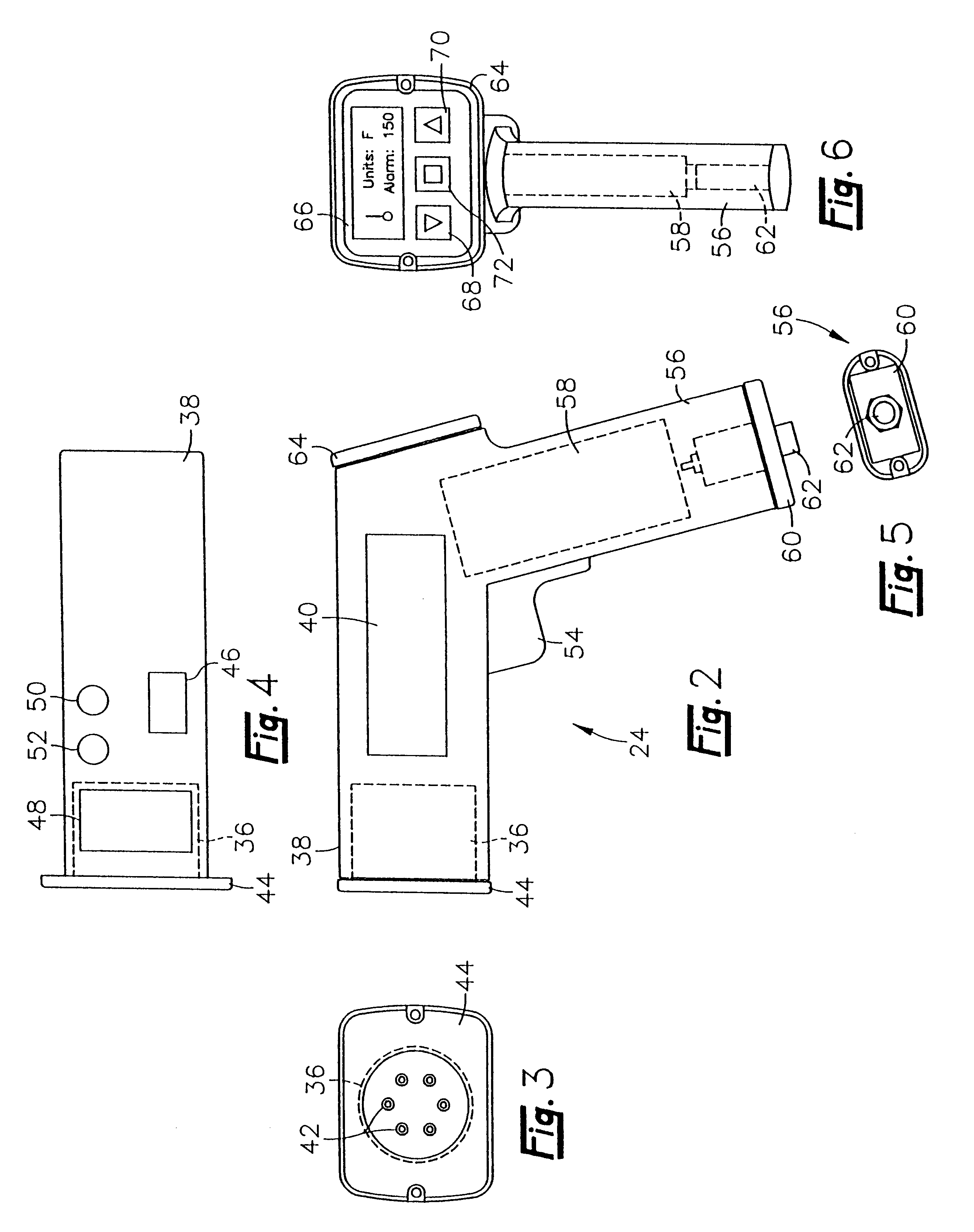
The ultrasonic monitoring system of the present invention effectively locates leaks of air, steam, or other gases from pressurized systems as well as arching and electrical corona, which may produce ultrasonic sounds. Furthermore, the ultrasonic monitoring system can also diagnose and analyze steam trap operation, bearing and gear defects, cavitation and surging in pumps and compressors, lubrication problems in dynamic equipment, valve operation, steam lines, and piston friction and detonation problems in reciprocating equipment.

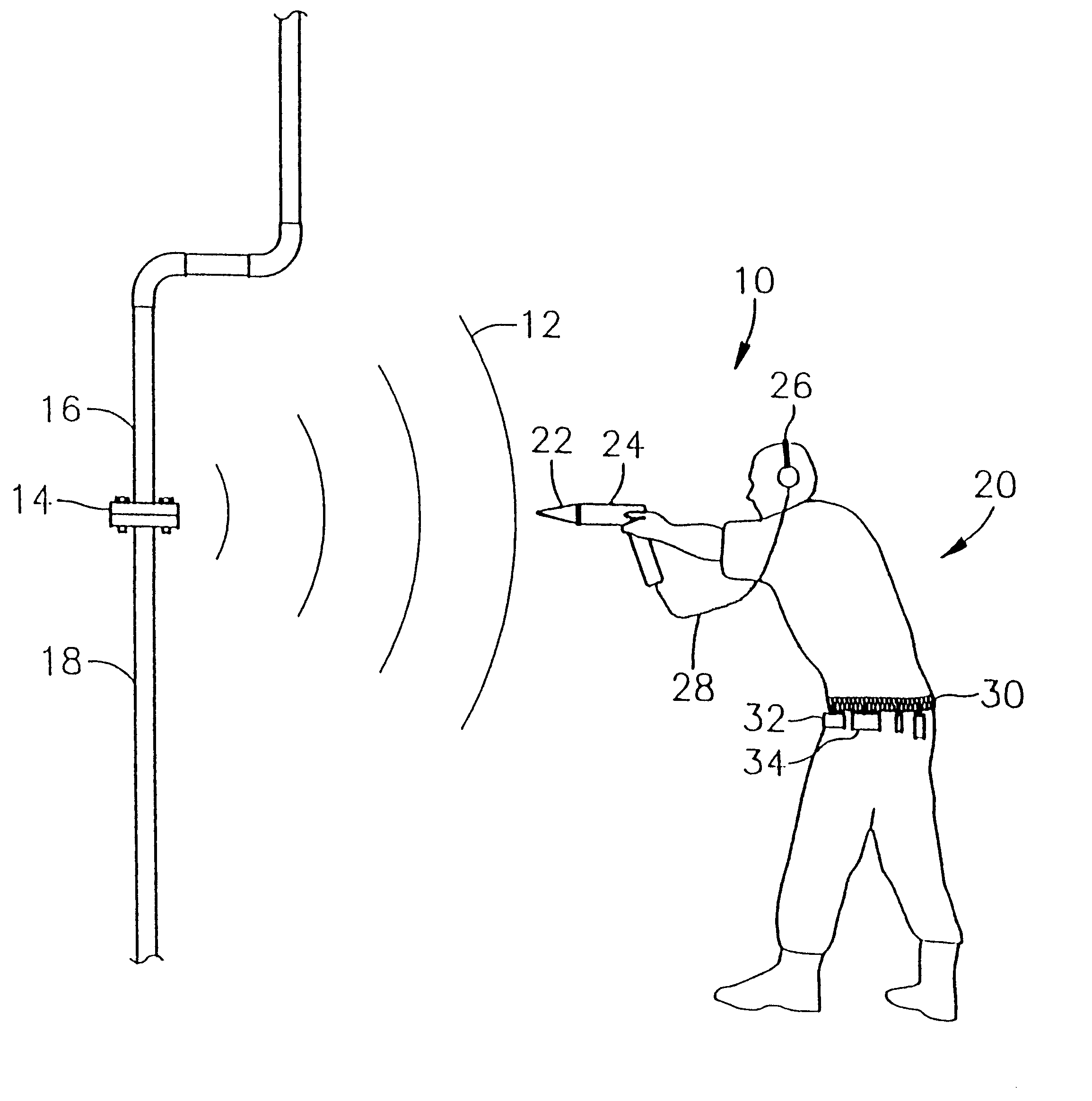
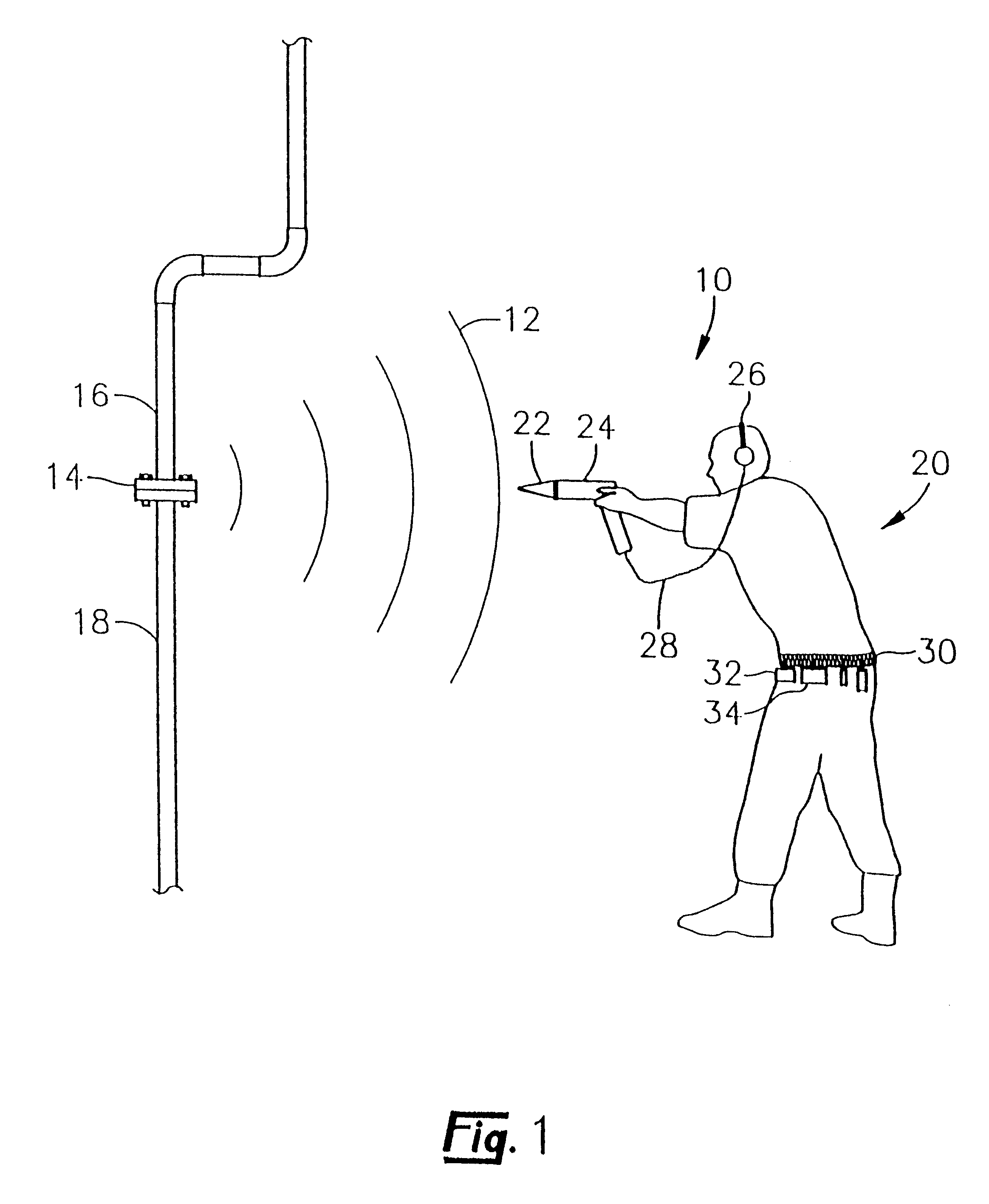
Referring now to FIG. 1, an especially preferred ultrasonic monitoring system 10 for detecting and monitoring ultrasonic sound waves 12 is shown. The ultrasonic sound waves 12 are emanating from the intersection 14 of two abutting pipes 16 and 18. In the case of leak detection, the ultrasonic monitoring system 10 is principally used by the operator 20 to determine the location from which the ultrasonic sound waves 12 are emanating. The ultrasonic monitoring...


PUM

PropertyMeasurementUnit
frequencyaaaaaaaaaa
frequencyaaaaaaaaaa
resonant frequenciesaaaaaaaaaa

Abstract

An ultrasonic monitoring apparatus is provided for use by an operator in detecting ultrasonic vibrations and sound waves. The ultrasonic monitoring apparatus consists of a hand held device with a sensor socket that allows a variety of different types of sensors to be interchangeably installed in the hand held device. These sensors include both contact and airborne ultrasonic sensors as well as a combination temperature and ultrasonic sensor that allows the operator to simultaneously monitor the surface temperature of an object and the ultrasonic vibrations produced by the object. Identification information corresponding to the type of sensor is encoded on the individual sensors. The identification information is read by an identification circuit located in the hand held device. This identification information allows the hand held device to configure itself to operate with the type of sensor installed in the socket.

Description

1. Field of the InventionIn general, the present invention relates to a device for detecting and monitoring ultrasonic sound waves. In particular, the present invention relates to a portable ultrasonic monitoring instrument that utilizes multiple sensors which can be interchangeably installed into a sensor socket to obtain measurements such as ultrasonic sound wave strength and surface temperature that are useful in detecting machinery defects and equipment failures.2. Background of the InventionThe normal frequency range for human hearing is roughly 20 to 20,000 hertz. Ultrasonic sound waves are sound waves that are above the range of human hearing and, thus, have a frequency above about 20,000 hertz. Any frequency above 20,000 hertz may be considered ultrasonic. Most industrial processes, including almost all sources of friction, create some ultrasonic noise. For example, leaks in pipes, machinery defects and electrical arcing produce ultrasonic sound waves that have a frequency t...

Claims


Application Information

Patent Timeline
Patent Type & Authority Patents(United States)
IPC IPC(8): G01N29/12G01N29/14G01H1/00G01H17/00
CPCG01H1/00G01H3/00G01N2291/02863G01N2291/02881
Inventor JOHNSON, WILLIAM S.PIETY, KENNETH R.ROBINSON, JAMES C.VAN VOORHIS, JAMES B.
Owner COMPUTATIONAL SYST
Why Eureka
Try Eureka