
Take-up pulley in an image processor

a technology of image processor and pulley, which is applied in the direction of gearing, printers, hoisting equipment, etc., can solve the problems of high manufacturing cost of the pulley itself and a correspondingly high manufacturing cost of the image processor as a whole, and may not achieve the desired roundness of the drum 51, so as to achieve the effect of cost reduction

Inactive Publication Date: 2001-04-24
FUJI PHOTO OPTICAL CO LTD
View PDF2 Cites 12 Cited by
  • Summary
  • Abstract
  • Description
  • Claims
  • Application Information

AI Technical Summary

Benefits of technology

to provide a take-up pulley used in an image processor so improved that not only an effective cost reduction but also an out of roundness desired for the pulley drum-like section can be achieved even when the take-up pulley is formed by molding of a suitable synthetic resin material.
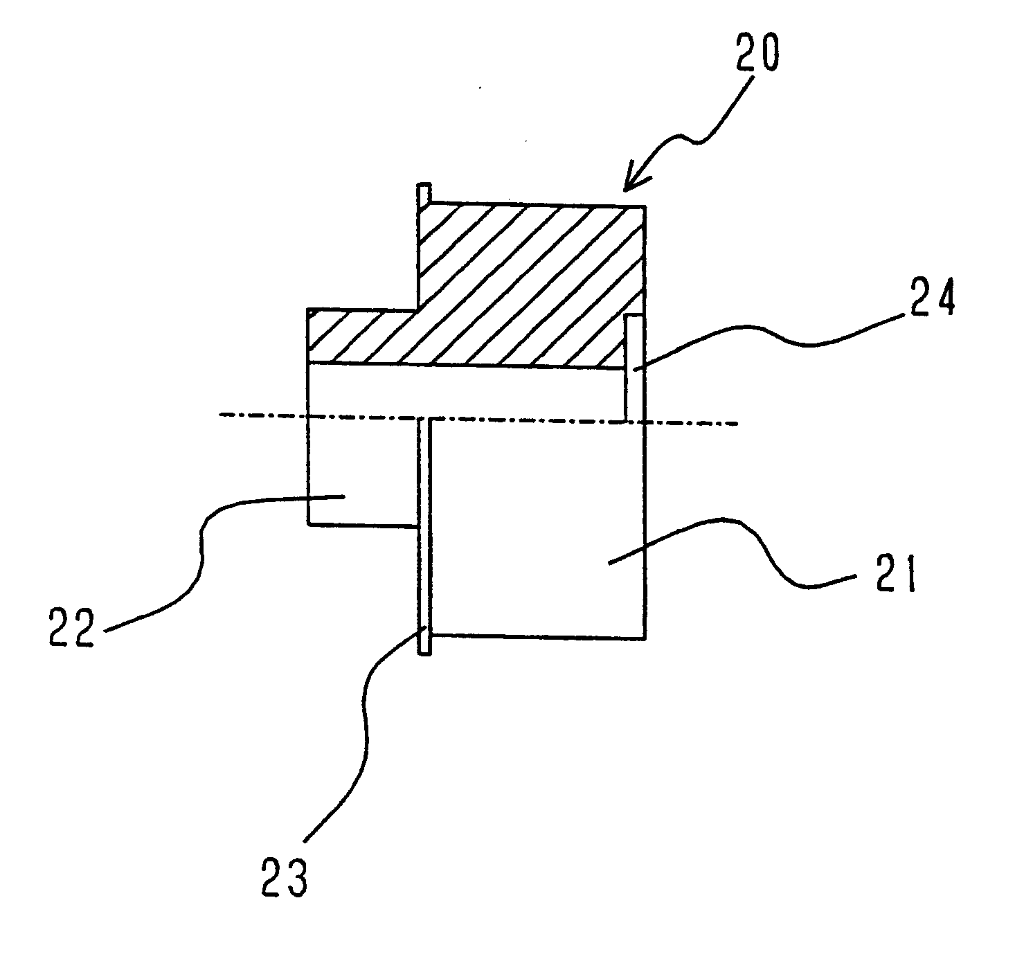
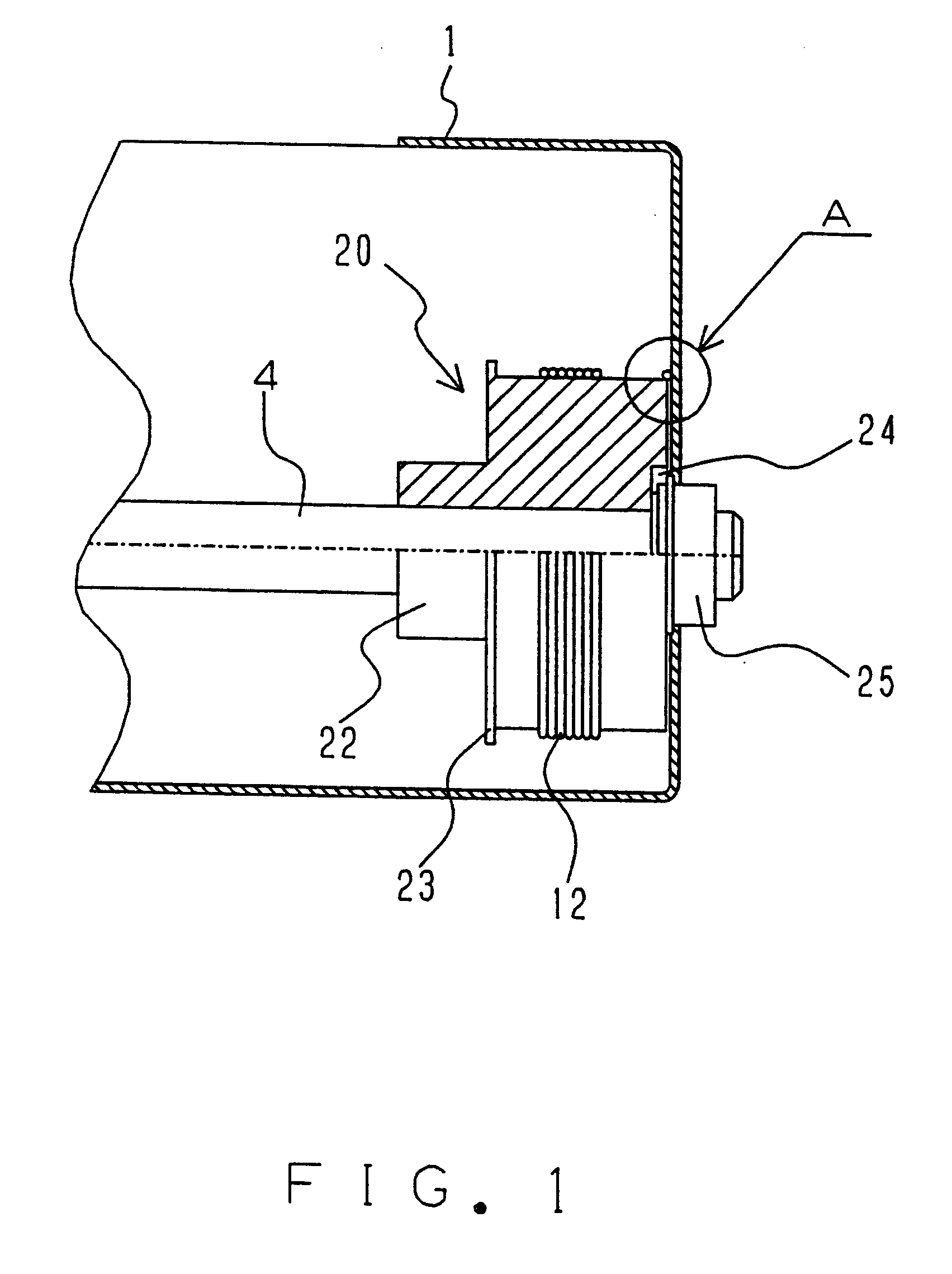
The take-up pulley is made of synthetic resin material by a suitable molding process such as an extrusion molding, and, therefore, the take-up pulley can be easily manufactured at a relatively low cost. Additionally, only one end of the drum-like section is formed with said stopper flange so that the mold can be opened axially of the drum-like section and thereby an out of roundness desired for the drum-like section can be reliably obtained.
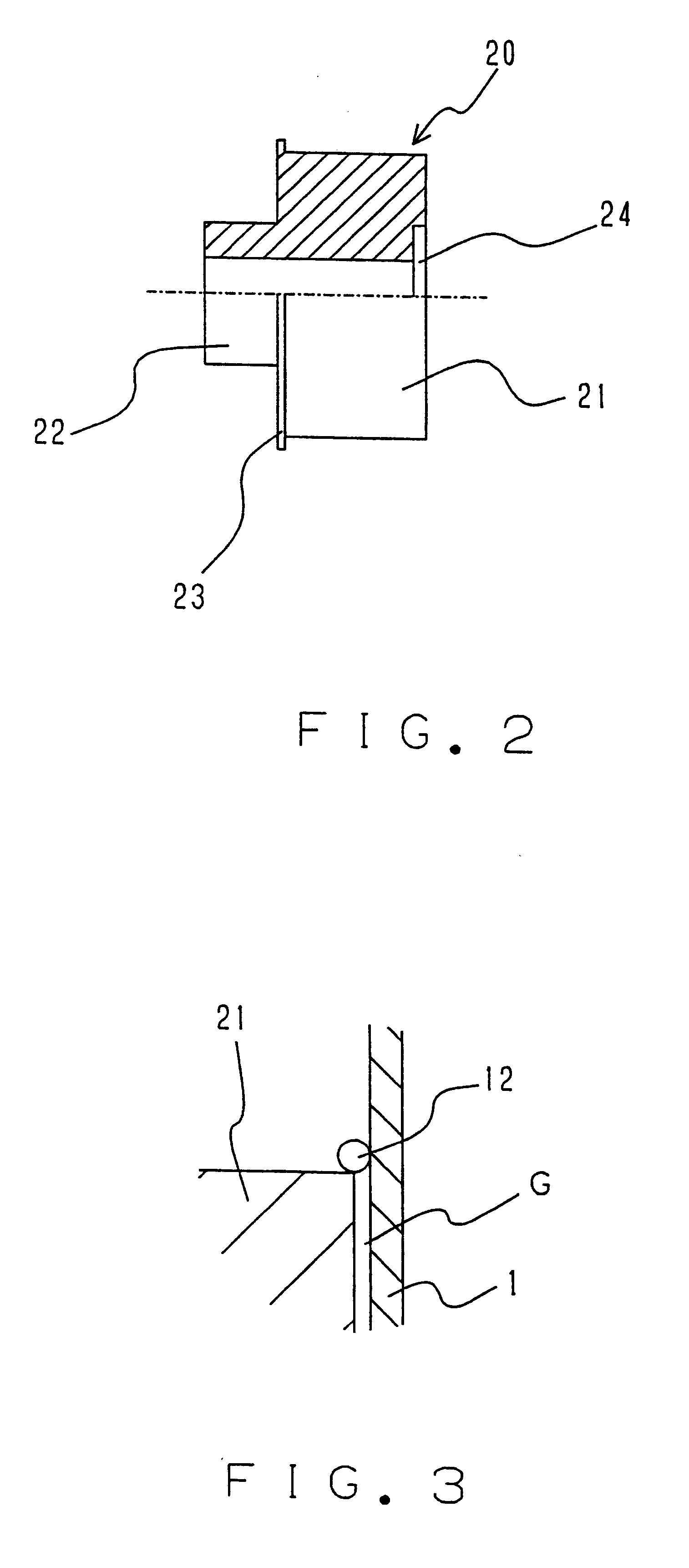
Preferably, said take-up pulley is fixedly mounted on said driving shaft so that a gap smaller than a diameter of said wire may be formed between said end surface of said drum-like section opposite said boss-like projection and an inner wall of a housing of said image processor. Said collar is formed at only one end of the drum-like section so that, in a molding process of the take-up pulley, the mold can be opened axially of the drum-like section. Although slipping off of the wire might otherwise occur at the other end of the drum-like section, such slipping off of the wire can be reliably prevented by positioning said other end of the drum-like section closely adjacent the inner wall of the housing.

Problems solved by technology

However, the take-up pulley 50 of the prior art, made of metallic material or sintered metal, necessarily leads to a high manufacturing cost of the pulley itself and a correspondingly high manufacturing cost of the image processor as a whole.
Such arrangement of the mold is inevitably accompanied with the problem that a desired out of roundness may not be ensured for the drum 51.

Method used


Image

  • Take-up pulley in an image processor
  • Take-up pulley in an image processor
  • Take-up pulley in an image processor

Examples


Embodiment Construction

Details of the inventive take-up pulley in an image processor will be more fully understood from the description of the preferred embodiments given hereunder with reference to the accompanying drawings.

A carrier driving mechanism is briefly described with reference to FIG. 4. A housing 1 for the image processor is formed with a pair of guides la defined by steps extending inwardly from respective inner surfaces of transversely opposite side walls of said housing 1. These guides la extend longitudinally of said housing 1 so that a first carrier 2 and a second carrier 3 placed on said guides la may be slidably moved thereon. Carriers 2, 3 are provided with reflectors (not shown) in an appropriate manner so as to define an optical path serving to direct an image on an original (not shown) placed upon a top surface of the housing 1 toward a pick-up element such as a CCD (not shown). The image is read from the original as these carriers 2, 3 slidably move along the original to scan it. D...


PUM


Abstract

A take-up pulley for a carrier in an image processor has a drum-like section with a boss-like projection extending from one end. In one embodiment, a recess is formed at the other end of the drum-like section for receiving a bearing. A stopper flange is formed at the end of the drum-like section adjacent the boss-like projection. The take-up pulley can be formed by a suitable molding process such as extrusion using the mold adapted to be opened axially. The take-up pulley is fixedly mounted on the driving shaft in the housing of an image processor so that a gap G smaller than a diameter of a drive wire may be formed between the end surface of the drum-like section and an inner wall of the housing. In another embodiment, an annular stopper plate is affixed to the end of the drum section instead of the recess.

Description

1. Field of the InventionThis invention generally relates to an image processor such as a copying machine or a scanner functioning to read images of an original represented on a paper sheet or the like and then to subject these images to various kinds of processing and more particularly to a take-up pulley mounted on a driving shaft in such image processor to take up / let out the wire operatively associated with a carrier adapted to scan the original and thereby to transmit a drive force from an electric motor to said carrier.2. Description of the Related ArtThe function of the carrier in the image processor is to pick up images to be processed from the original and to guide them to an image processing unit such as a CCD. To achieve this, the carrier is provided with a reflector or the like adapted to form an optical path extending from the original to said CCD. The carrier thus scans the original and picks up the images on said original. The carrier is operatively associated with a ...

Claims


Application Information

Patent Timeline
Patent Type & Authority Patents(United States)
IPC IPC(8): G03G15/04H04N1/10G03B27/50F16H55/36H04N1/107
CPCG03G15/04H04N1/1013H04N1/1026Y10T74/18832Y10T74/18848
Inventor HAYASHI, EIICHI
Owner FUJI PHOTO OPTICAL CO LTD
Learn More