
Method of cleaning transparent device in a thermal process apparatus, thermal process apparatus and process using the same thermal process apparatus

a transparent device and thermal process technology, applied in the direction of cleaning process and apparatus, cleaning process using liquids, chemistry apparatus and processes, etc., can solve the problems of affecting the yield of the process, the flakes of coating material may peel off and contaminate the wafer, and the light passing through the quartz window surface is non-uniform, so as to reduce the manufacturing cost and increase the process yield

Inactive Publication Date: 2009-04-30
UNITED MICROELECTRONICS CORP
View PDF5 Cites 0 Cited by
  • Summary
  • Abstract
  • Description
  • Claims
  • Application Information

AI Technical Summary

Benefits of technology

[0008]The present invention is to provide a method of cleaning a transparent device in a thermal process apparatus, a thermal process and a thermal process device, wherein the various problems in the conventional practice are obviated and the uniformity of the light source through the transparent device is enhanced to lower the manufacturing cost and to raise the process yield.
[0031]The apparatus of the invention includes the surface cleaning device for cleaning the coating material on the surface of the transparent device or altering the coating material to become transparent inside the thermal process apparatus. Hence, any effect of the coating material on the transparent device is prevented to improve the process yield. Moreover, the method and the process of the present invention can effectively clean the surface of the transparent device and remove the coating material on the surface of the transparent device. Hence, the process yield is increased to lower the replacement rate of the transparent device and to effectively cost down the production.

Problems solved by technology

The coating material on the surface will cause the light that passes through the quartz window surface to be non-uniform.
Hence, the yield of the process is affected.
Further, as the coating material the quartz window surface accumulates to a considerable thickness, the flakes of the coating material may peel off to contaminate the wafer.
Ultimately, the process yield is lowered and the products may become defective.
This approach not only affects the up-time of the apparatus, the repairing cost and defective products would increase significantly.

Method used


Image

  • Method of cleaning transparent device in a thermal process apparatus, thermal process apparatus and process using the same thermal process apparatus
  • Method of cleaning transparent device in a thermal process apparatus, thermal process apparatus and process using the same thermal process apparatus

Examples


Embodiment Construction

[0035]The present invention can be better understood by way of the following embodiments but which are not to be construed as limiting the scope of the invention.

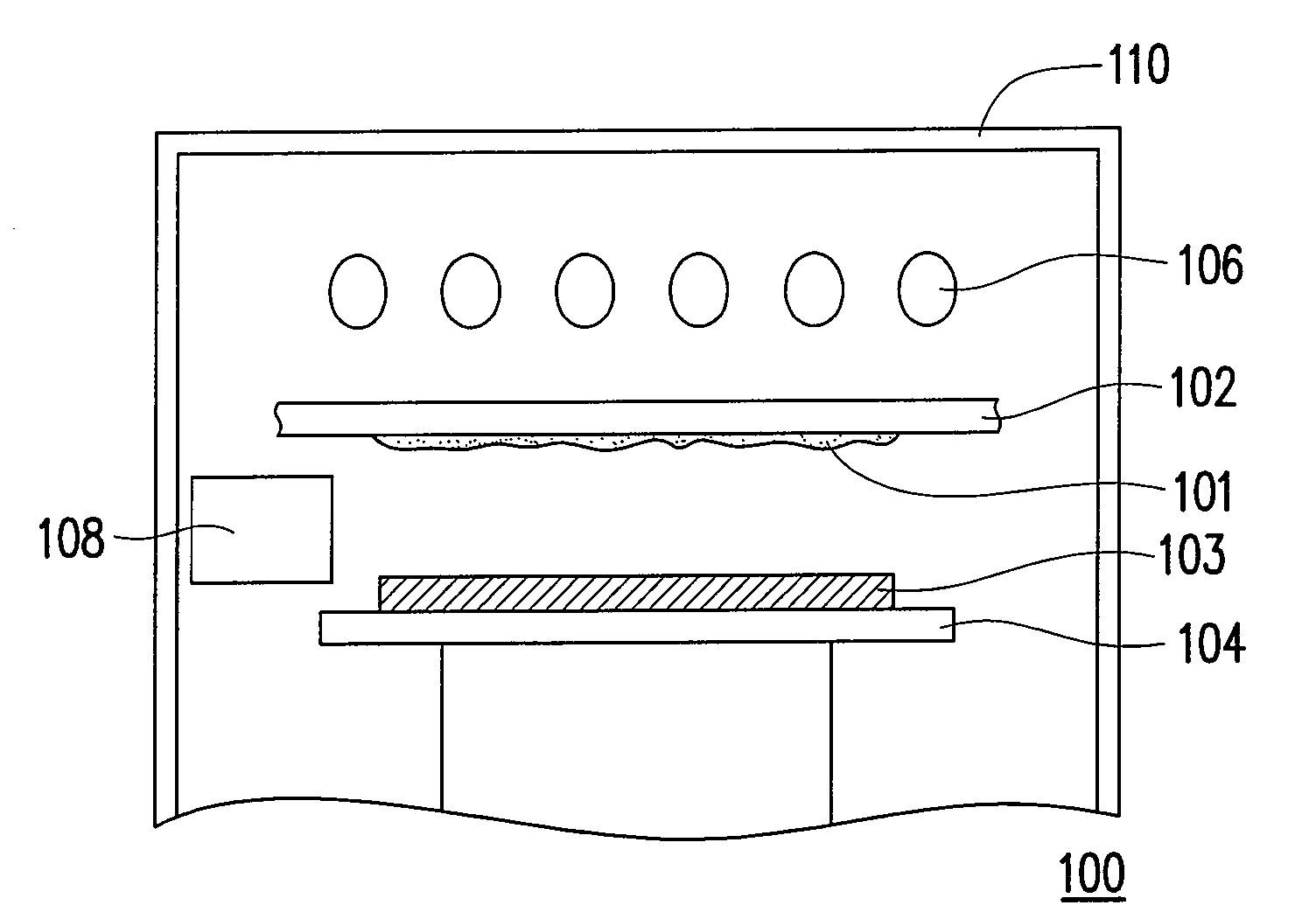
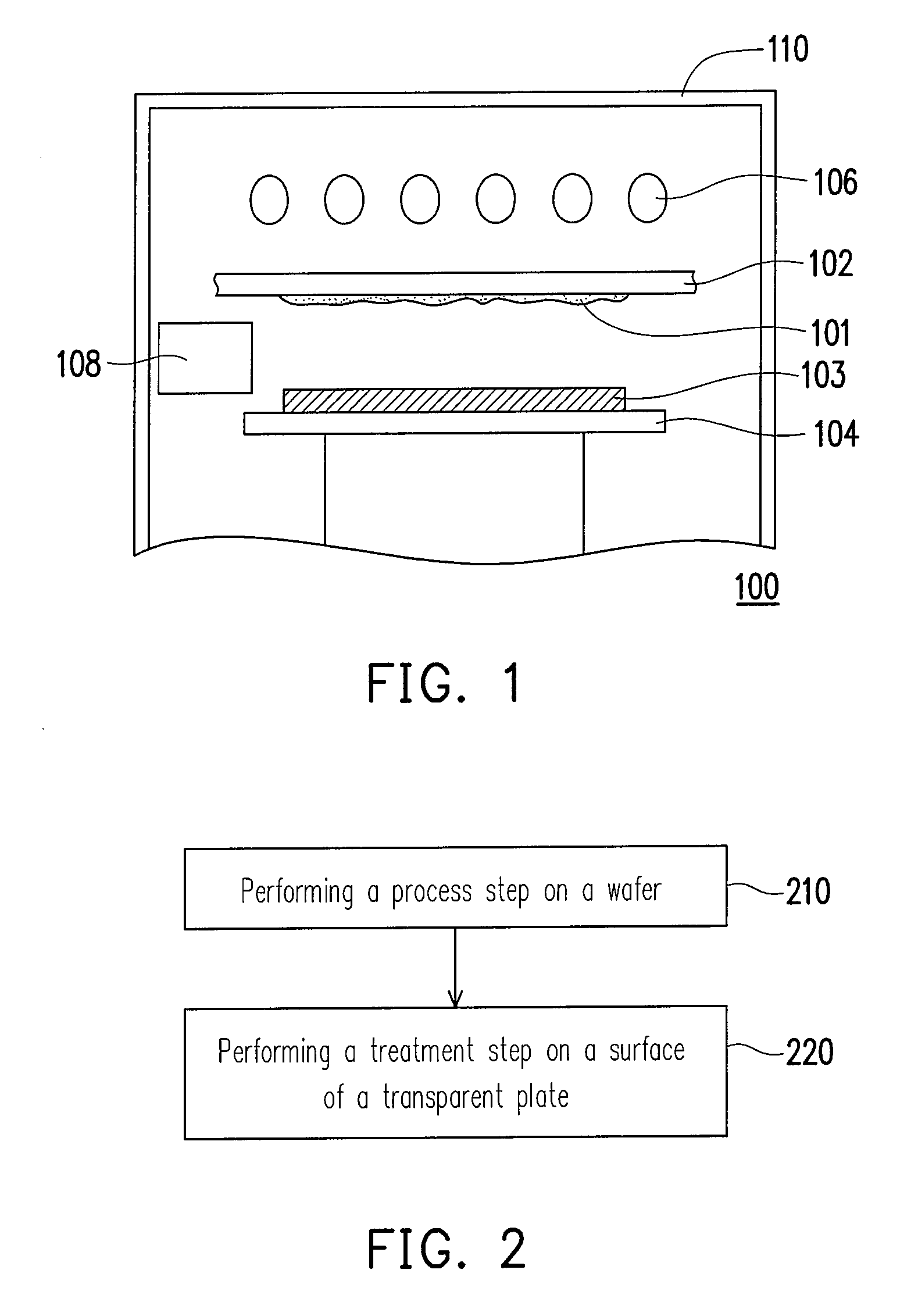
[0036]Referring to FIG. 1, FIG. 1 is a schematic diagram illustrating a thermal process apparatus according to an embodiment of the present invention. The thermal process apparatus 100 is applicable for a thermal treatment in typical semiconductor fabrication process. More particularly, the thermal process apparatus 100 is applicable for a rapid thermal processing (RTP). For example, the thermal process apparatus 100 is applicable in a salicide process, a deposition process for forming silicon oxide, silicon nitride and silicon oxynitride, a low dielectric material (low-k) treatment process and a ultra-violet curing process. The thermal process apparatus 100 of the invention is also applicable in performing a series of processes including but not limited to a process of lattice rearrangement and stress-concentration dissipa...


PUM


Abstract

A method of cleaning a transparent device in a thermal process apparatus, wherein the transparent device is disposed in a chamber of a thermal process apparatus, and the transparent device includes a wafer holder for carry a wafer disposed under the transparent device, and an energy source output device disposed above the transparent device in the chamber, is provided. The method of the present invention includes performing a surface treatment step to clean a surface of the transparent device.

Description

BACKGROUND OF THE INVENTION[0001]1. Field of Invention[0002]The present invention relates to a semiconductor apparatus and a semiconductor process using the apparatus. More particularly, the present invention relates to a method of cleaning a transparent device in a thermal process apparatus, a thermal process and a thermal process apparatus.[0003]2. Description of Related Art[0004]The semiconductor industry is being developed toward the direction of the manufacturing technology of low cost and high integration. Hence, the rapid thermal process (RTP) has been gradually replacing the conventional heat treatment step conducted in high temperature furnace. The importance of the rapid thermal process in the future integrated circuit processing is undeniable. Further, the technology of rapid thermal process has been applied in many semiconductor processes in the field of research and commercially.[0005]In general, the equipments for the RTP mainly include a wafer holder for carrying a wa...

Claims


Application Information

Patent Timeline
IPC IPC(8): B08B5/00B08B13/00B08B7/00
CPCB08B7/00H01L21/67028B08B7/0035
Inventor WANG, YU-YUNGWU, SHIN-LONGLIANG, CHAO-HULIN, SHENG-YAOSHIH, HUI-SHENCHIEN, YU-FANG
Owner UNITED MICROELECTRONICS CORP
Learn More