Swimming pool chlorinator with adjustable slits

a chlorinator and swimming pool technology, applied in the direction of liquid displacement, separation process, dissolving, etc., can solve the problems of pool that is not receiving an adequate amount of chlorine, almost never achieved chlorination throughout the swimming pool, etc., to achieve the effect of low cost, simple construction and low cos

Inactive Publication Date: 2001-04-24
YASSIN IHSSAN F
View PDF8 Cites 25 Cited by
  • Summary
  • Abstract
  • Description
  • Claims
  • Application Information

AI Technical Summary

Benefits of technology

Another objective of the present invention is to construct a swimming pool chlorinator which is simple in construction and can be manufactured relatively inexpensively and thereby sold to the ultimate consumer at an inexpensive price.
Another objective of the present invention is to construct a chlorinator which can be quickly and easily mounted on the sidewall surface of a swimming pool in any desired location within the swimming pool and also can be easily and quickly removed from the swimming pool when such is desired.

Problems solved by technology

However, one problem with a floating dispenser is that it commonly moves to one particular location of the swimming pool and stays in that location.
However, also with this type of chlorinator, even chlorination throughout the swimming pool is almost never achieved.
There always seems to be at least one area of the swimming pool that is not receiving an adequate amount of chlorine.

Method used


Image

  • Swimming pool chlorinator with adjustable slits
  • Swimming pool chlorinator with adjustable slits
  • Swimming pool chlorinator with adjustable slits

Examples


Embodiment Construction

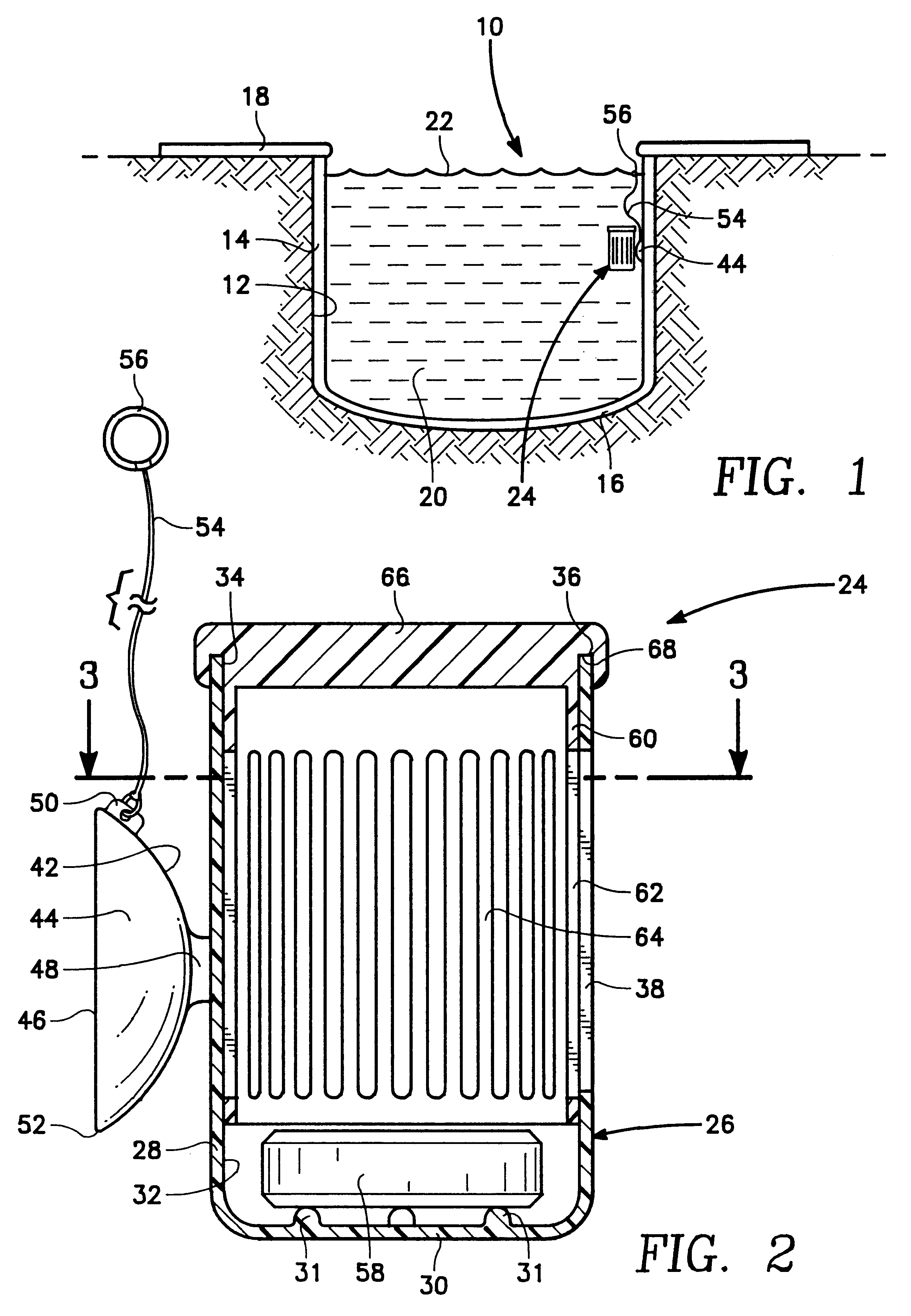
Referring particularly to the drawings, there is shown in FIG. 1 a swimming pool 10 that is formed within a cavity 12 within the ground. The swimming pool 10 has a wall surface 14 and a floor 16. Surrounding the swimming pool 10 is a coping 18. The swimming pool 10 is to be filled with water 20 which has a surface 22. Chlorinator 24 of this invention is to be installed generally on the wall surface 14 beneath the surface 22.

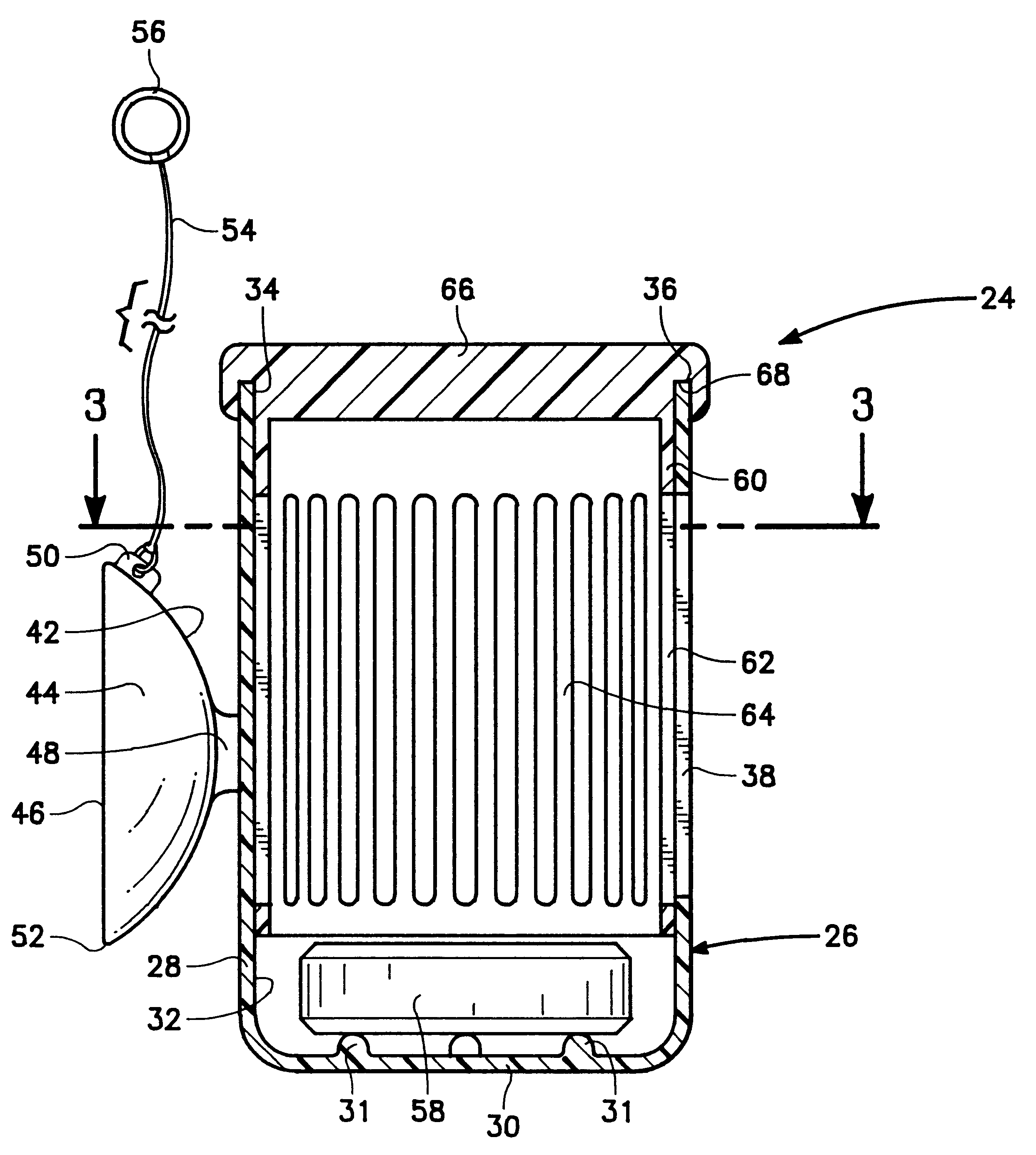
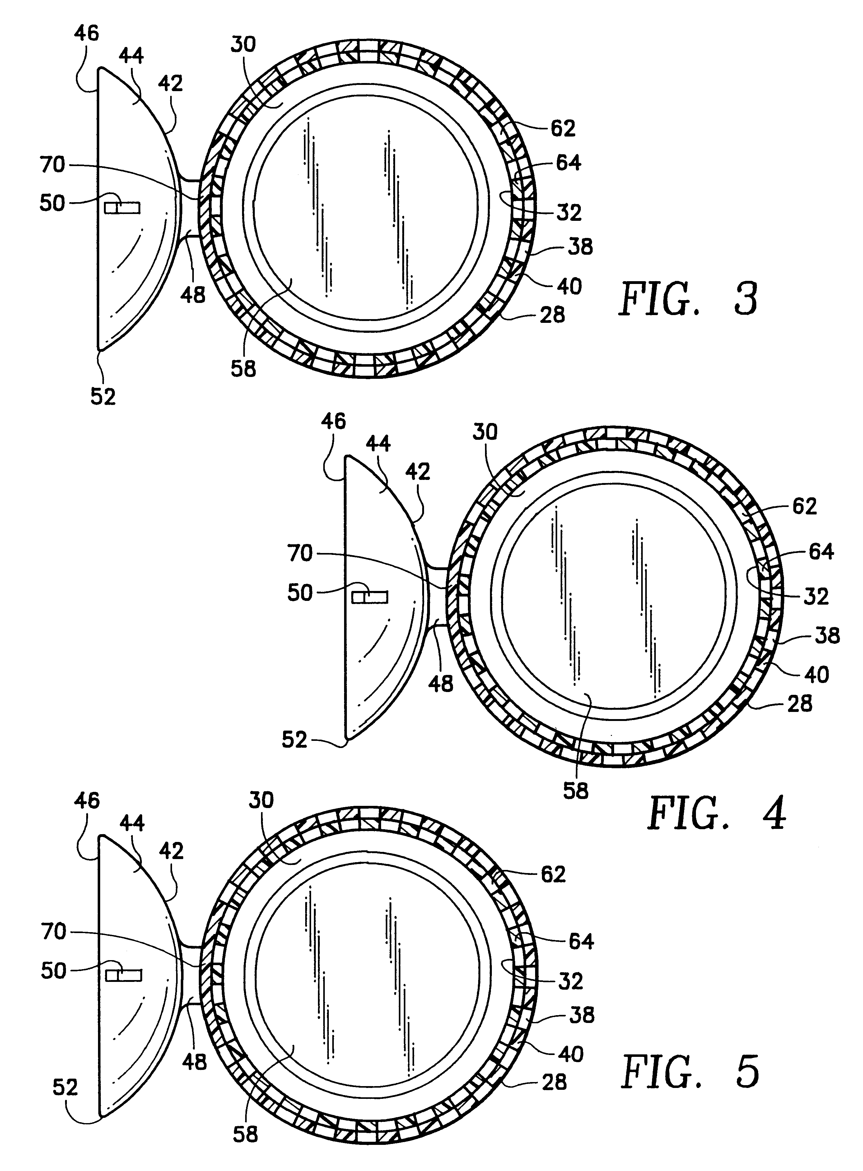
The chlorinator 24 comprises a cylindrically shaped housing 26. The cylindrically shaped housing 26 includes a 20 sidewall 28 and a closed bottom 30. The housing 26 includes an internal chamber 32. The housing 26 has an open upper end 34 which is enclosed by an annular sidewall edge 36.

Longitudinally formed within the housing 26 are a series of elongated slits 38. There are twenty-one in number of the slits 38 located circumferentially around the housing 26. Each of the slits 38 are of the same width and separating each directly adjacent pair of slits 38 is a thi...


PUM

PropertyMeasurementUnit
lengthaaaaaaaaaa
lengthaaaaaaaaaa
period of timeaaaaaaaaaa

Abstract

A swimming pool chlorinator that utilizes a cylindrical housing that has an internal chamber. Within the internal chamber is concentrically mounted in a close fitting manner a valve member. The sidewall of the housing has a series of elongated slits and also the valve member has a series of similar elongated slits. The housing has mounted thereon at least one suction cup with the suction cup to be securable to a swimming pool wall surface or other surfaces associated with a swimming pool and beneath the surface of the water in the pool. Within the internal chamber of the housing is located one or more chlorine tablets. The valve member is to be adjusted relative to the housing so that the slits of the housing are unrestricted permitting free flow of water through the housing or the slits are restricted partially thereby limiting the amount of flow of water through the internal chamber. As the water is conducted through the internal chamber, the chlorine tablet is dissolved within the water which chlorinates the water of the swimming pool when this water is conducted exteriorly of the housing.

Description

BACKGROUND OF THE INVENTION1) Field of the InventionThe subject matter of this invention pertains to a device for introducing a chemical into a pool of liquid and more particularly to a chlorinator for a swimming pool.2) Description of the Prior ArtIn order to keep a swimming pool sanitary and to keep algae from growing within the swimming pool, it is necessary to add chlorine on a regular basis to the swimming pool water. The vast majority of swimming pool chlorinators are designed to supply chlorine on an automatic basis by adding chlorine over a period of time. One way in which chlorine can be added over a period of time is by utilizing of a tablet that is designed to dissolve at a certain rate. Normally, these tablets take a period of days in order to completely dissolve.There are several different types of chlorinators that use dissolving tablets. One particular type of chlorinator comprises a floating dispenser where the dispenser floats around the swimming pool with the table...

Claims


Application Information

Patent Timeline
Patent Type & Authority Patents(United States)
IPC IPC(8): C02F1/68E04H4/00E04H4/12C02F1/76
CPCC02F1/688E04H4/1281B01F1/0027C02F1/76C02F2103/42Y10T137/4891B01F21/22
Inventor YASSIN, IHSSAN F.
Owner YASSIN IHSSAN F
Why Eureka
Try Eureka