Plasma generator pulsed direct current supply in a bridge configuration

a direct current supply and plasma generator technology, applied in the field of pulsed dc power supplies, can solve the problems of high-frequency voltage sources that are difficult to operate, dangerous to operate, and expensive to construct and maintain

Inactive Publication Date: 2001-04-24
ADVANCED ENERGY IND INC
View PDF36 Cites 114 Cited by
  • Summary
  • Abstract
  • Description
  • Claims
  • Application Information

AI Technical Summary

Benefits of technology

A first advantage of the present invention is that the current controlled power source provides a device for accurately controlling the amount of current that is applied to the plasma chamber despite changes in the resistance of the plasma. The switches that control the flow of current through the plasma chamber can also be utilized to shunt current. Multiple electrodes can be used in conjunction with either a single power source or multiple power sources to increase the deposition capabilities of the plasma chamber. Multiple electrodes allow for multiple target surfaces when each of the electrodes is sequentially employed as the cathode target surface.

Problems solved by technology

These high-frequency voltage sources are expensive to construct and maintain, as well as dangerous to operate.
Despite the advantages that constant voltage pulsed power sources provide, problems exist with regard to generation of excessive currents and spark discharges in the plasma chamber.
As part of this problem, it has been found that as the current through a plasma increases, the resistance of the plasma decreases in an exponential manner to almost zero.
Small changes in the voltage level of a voltage power source result in large changes in the current.
The high power required to produce the desired plasma temperatures places extreme demands on the power supply.

Method used


Image

  • Plasma generator pulsed direct current supply in a bridge configuration
  • Plasma generator pulsed direct current supply in a bridge configuration
  • Plasma generator pulsed direct current supply in a bridge configuration

Examples


Embodiment Construction

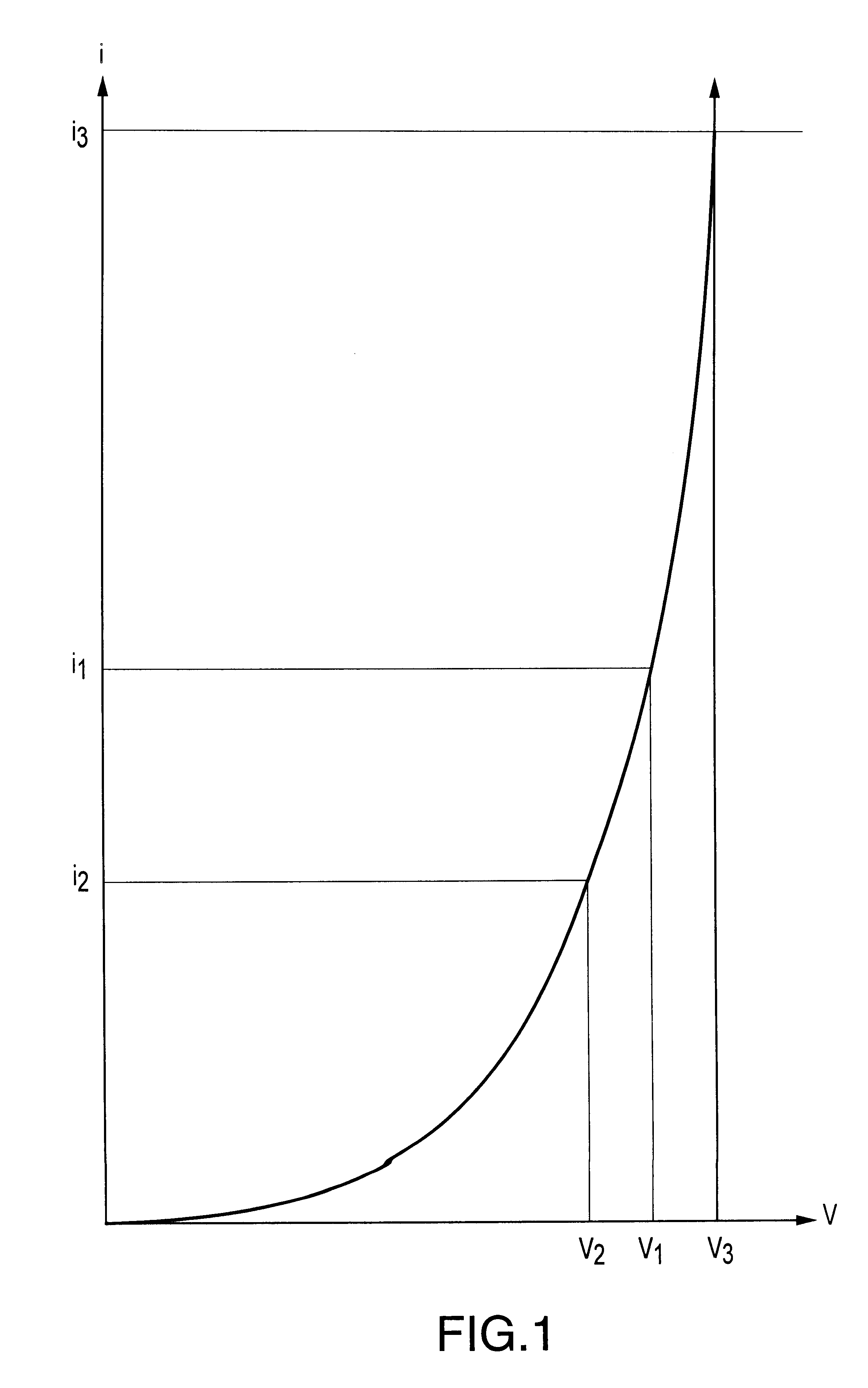
FIG. 1 illustrates the advantages of driving the plasma generator with a current source through current reversing switches. FIG. 1 shows the current / voltage characteristics of a typical plasma chamber. As shown in FIG. 1, as the voltage increases, the current through the plasma chamber rises exponentially. As is readily apparent from FIG. 1, once the slope of the current versus voltage curve of FIG. 1 exceeds 45 degrees, it is better to control the power source with current rather than with voltage. Accordingly, at the operating point of a current i.sub.1, a small change in voltage can produce a large change in current around i.sub.1. For example, although a small change in voltage from v.sub.1 to v.sub.2 only produces a relatively small change in current from i.sub.1 to i.sub.2 an equally small change in voltage from v.sub.1 to v.sub.3 causes a very large change in current from i.sub.1 to i.sub.3. Thus, a voltage source driving the plasma chamber is very susceptible to arc discharg...


PUM

PropertyMeasurementUnit
constant currentsaaaaaaaaaa
currentaaaaaaaaaa
constant direct currentsaaaaaaaaaa

Abstract

Current controlled power sources are disclosed that are capable of generating currents in low resistance, high temperature plasmas that are regulated to prevent the generation of excessive currents in the plasma. Current reversing switches are provided that control the flow of a direct current in a plasma chamber between various electrodes. Multiple power sources are provided in association with shunt switches for delivering a plurality of sources of direct current in various directions between electrodes in a plasma chamber. Inductive impedance can be provided in switch paths to cause a source of direct current to flow through a plasma chamber in various directions between electrodes.

Description

1. Field of InventionThe present invention pertains generally to power supplies and more particularly to pulsed DC power supplies that are used for generating plasmas that are used in thin film processing techniques for etching, deposition, etc.2. DefinitionsAlternating polarities means a current flow at any particular point in a circuit or plasma that changes direction, or a voltage at any particular point in a circuit that changes magnitudes around any desired neutral voltage.Current connections means locations or points in a circuit that are coupled to electrodes of a plasma chamber.Current controlled power source means a power source that is capable of maintaining a substantially constant current for a wide range of load impedances and has a low amount of capacitively stored energy.Current reversing switches means any desired arrangement of switches that are capable of causing current to flow in different directions at a preselected location in a circuit.Direct current means cur...

Claims


Application Information

Patent Timeline
Patent Type & Authority Patents(United States)
IPC IPC(8): H01J37/32H05H1/46
CPCH01J37/32045H05H1/46
Inventor SCHOLL, RICHARD A.CHRISTIE, DAVID J.
Owner ADVANCED ENERGY IND INC
Why Eureka
Try Eureka