Broadband switching system

a switching system and broadband technology, applied in the field of broadband switching system, can solve the problems of not being able to meet the requirements of the customer,

Inactive Publication Date: 2001-04-24
BRITISH TELECOMM PLC
View PDF32 Cites 68 Cited by
  • Summary
  • Abstract
  • Description
  • Claims
  • Application Information

AI Technical Summary

Problems solved by technology

A disadvantage of all known permanent circuits is that the bandwidth remains assigned to the circuit, even when the customer has nothing to transmit.
This means that the customer may have to pay higher charges than would be obtained if the bandwidth was only made available when needed.
The assumption being made here is that charging is related to reserved bandwidth, and this is not necessarily correct in terms of the way public network operators may choose to charge for virtual circuits.
A difficulty with this approach is that it does not allow the customer to change the pattern of usage quickly, and it may only crudely reflect the usage required by the customer.
A difficulty with this approach is that some time delay will be incurred before the customer can start to use the virtual circuit.
A difficulty with this approach is that there is no internationally agreed standard for a bandwidth-requesting cell that would be recognised by the switching equipment produced by the various manufacturers.
This is because the required bandwidth may not immediately be available for allocation.
The above types of transmission do not operate satisfactorily when operating below the predetermined level of bandwidth (which is a pre-registered level that has been calculated as being sufficient for satisfactory operation) and thus if that level is not available, no bandwidth is allocated, i.e. lower bandwidth amounts are not allocated.
This will typically occur when the predetermined level of bandwidth is no longer available on the system.
Thus the user is taking a conscious risk that some of a message may not be transmitted when transmitting in this optional priority-downgrading mode.

Method used


Image

  • Broadband switching system
  • Broadband switching system
  • Broadband switching system

Examples


Embodiment Construction

In its preferred form, the invention is concerned with a broadband switching network which may form part of or may constitute a public switching network for the transmission of asynchronously transferred data cells between end-systems.

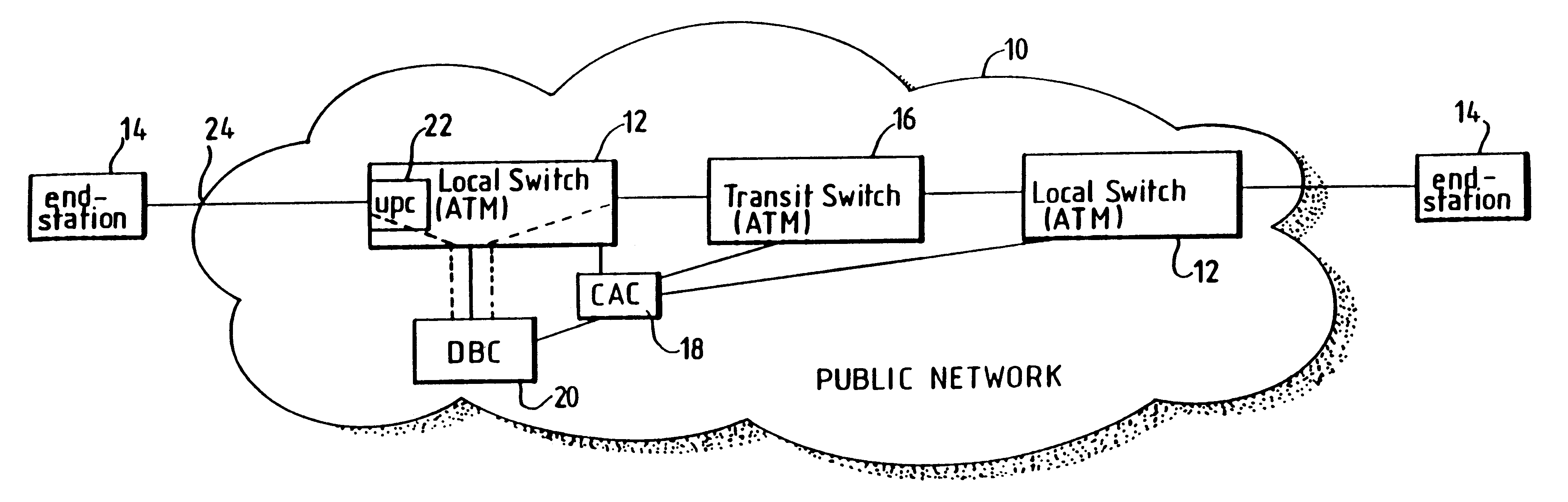
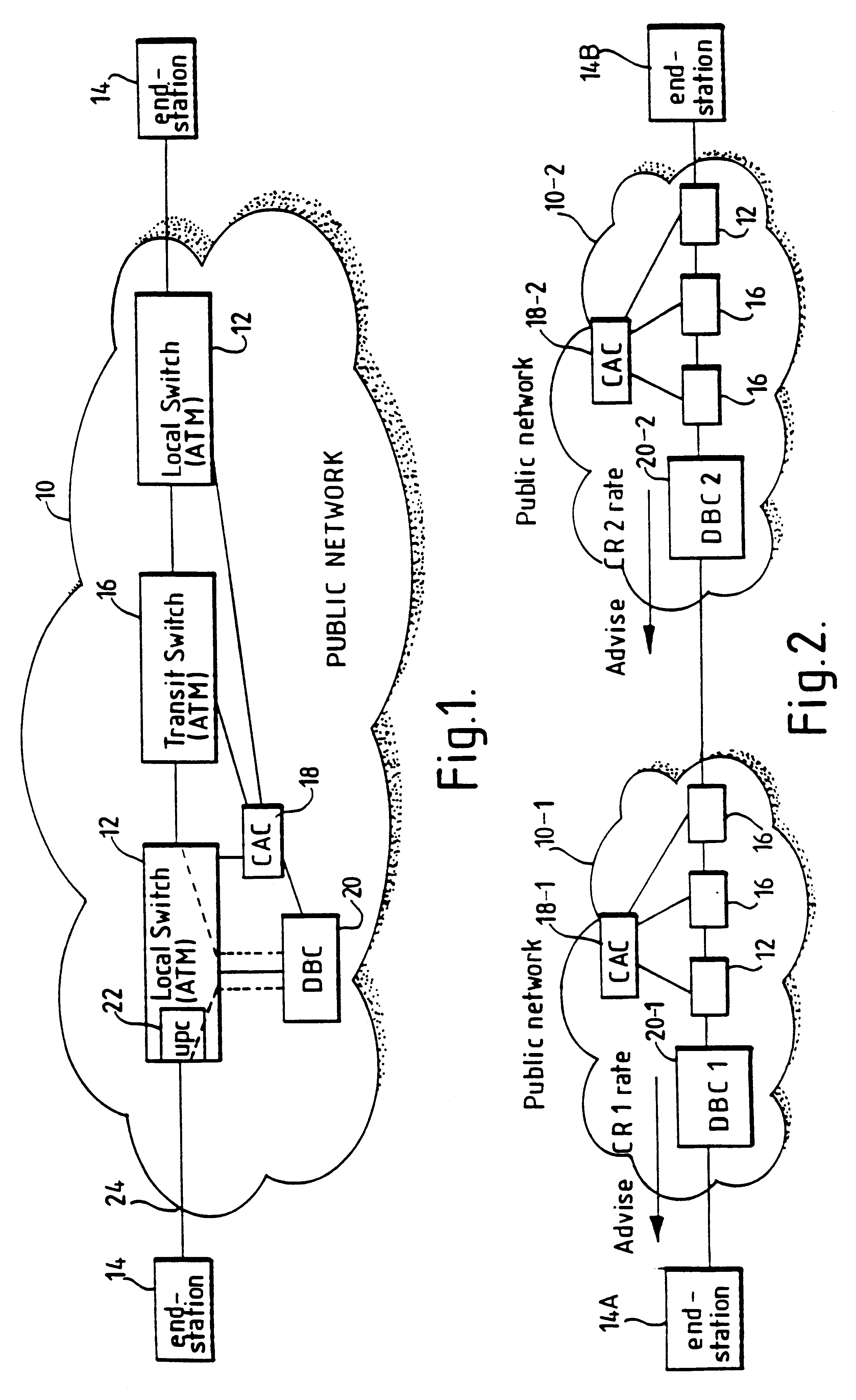
Referring to FIG. 1, the public network 10 has a plurality of switches operable in asynchronous transfer mode (ATM). In this simple example, the switches include two local switches 12 each having a port for connection to a respective end-system 14, and a transit switch 16 interconnecting the local switches 12. Associated with the switches is a connection admission control function (CAC) 18 and a dynamic bandwidth controller (DBC) 20 for controlling traffic entering the network through one of the local switches 12. This switch 12 also includes a usage parameter control device 22 for dynamically altering the priority of data cells received at the input port 24 of the network from the end-system 14.

It will be understood that, in practice, the network 10 w...


PUM


Abstract

In a broadband switching system for the switching of asynchronously transferred cells of data, a dynamic bandwidth controller (DBC) controls the application of data cells to an input port of the system. Data cells are supplied by a number of transmitting end-systems. When an end-system begins transmitting data cells, the DBC detects the presence of incoming cells and requests bandwidth from a connection admission control (CAC) forming part of the system. The switching system stores a table associating a number of signal sources connected to the ingress with respective predetermined transmission bandwidths and, preferably also, maximum delay times. When arrival of cells from one of the sources at the input port is detected, the DBC sends a request signal for the relevant predetermined bandwidth to the CAC and delays transmission of the cells until at least the predetermined bandwidth is allocated. This delay is typically effected by sending a cell rate indicator signal back to the input port for placing the source in a halt mode. If no allocation of bandwidth has occurred before the respective maximum delay time, bandwidth is allocated by robbing bandwidth form other signal sources.

Description

1. Field of the inventionThis invention relates to a broadband switching system for the switching of asynchronously transferred data cells, and to a method of switching asynchronously transmitted data cells.2. Related ArtBroadband switching networks for switching asynchronously transferred cells are known, in which a predetermined level of bandwidth is allocated to a transmission channel connecting a first customer to a second customer. In some of these known systems, a communications channel is provided over a significant period of time, effectively of the leased-line type, and manual measures are implemented in order to set up such a connection or to modify a connection according to the particular terminations and the level of traffic being conveyed. Consequently, it is usual for customers to incur a fixed rate charge as part of the overall charge for the connection, resulting in payment being made irrespective as to whether the connection is being used or not.Alternative systems ...

Claims


Application Information

Patent Timeline
Patent Type & Authority Patents(United States)
IPC IPC(8): H04Q11/04H04L12/56H04Q3/00H04L12/54H04L12/70
CPCH04L12/5602H04Q11/0478H04L2012/5615H04L2012/563H04L2012/5632H04L2012/5635H04L2012/5636H04L2012/5639H04L2012/5651H04Q11/04
Inventor SMITH, AVRIL J.ADAMS, JOHN L.
Owner BRITISH TELECOMM PLC
Why Eureka
Try Eureka