Redundant regulation valve

Inactive Publication Date: 2001-05-01
SN DETUDE & DE CONSTR DE MOTEURS DAVIATION S N E C M A
View PDF16 Cites 19 Cited by
  • Summary
  • Abstract
  • Description
  • Claims
  • Application Information

AI Technical Summary

Benefits of technology

The invention seeks to remedy the above-mentioned drawbacks and to enable operating safety of a fluid regulation valve to be increased without significantly increas

Problems solved by technology

The circuit shown diagrammatically in FIG. 5 does indeed provide total redundancy by complete duplication of all of the equipment (stop valve and regulation valve), but it suffers from major drawbacks, insofar as the system is bulky, having elements that lead to large mass, thereby making it unsuitable, particularly in space applications.
The totally redundant circuit is also expensive and can be difficul

Method used


Image

  • Redundant regulation valve
  • Redundant regulation valve
  • Redundant regulation valve

Examples


first embodiment

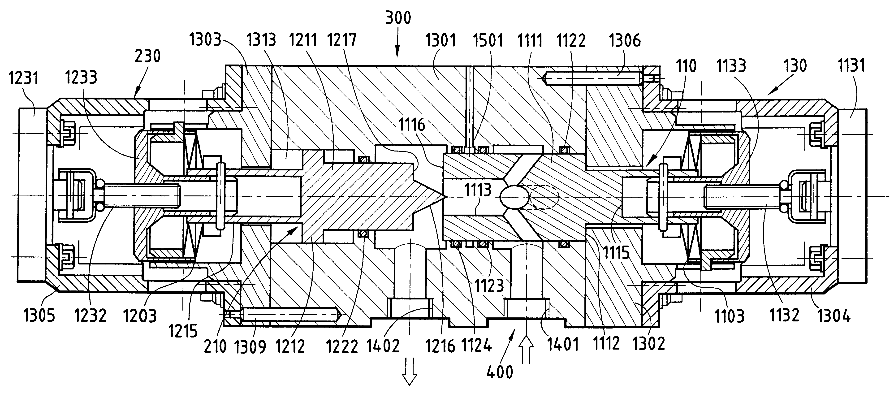
a regulation valve of the invention is described below with reference to FIGS. 7 to 9. FIGS. 7 to 9 show three variant embodiments having different configurations for the contact surfaces between the end of the main bar 110 and the end of the redundant bar 210. Apart from these different shapes for the contact surfaces, the remainder of the component elements of the valve are identical in all three variants and they are given the same references. The first embodiment is described initially in greater detail with reference to FIG. 7, which relates to a valve having throttle bars that are movable in translation.

The valve body 300 of FIG. 7 comprises a central portion 1301 and two lateral portions 1302 and 1303 placed against the central portion 1301 and fixed thereto by link elements 1306 and 1309. The central portion 1301 of the valve body 300 defines a passage 400 for fluid flow having an inlet orifice 1401, an outlet orifice 1402, and cavities 1403 and 1404 that can be selectively ...

second embodiment

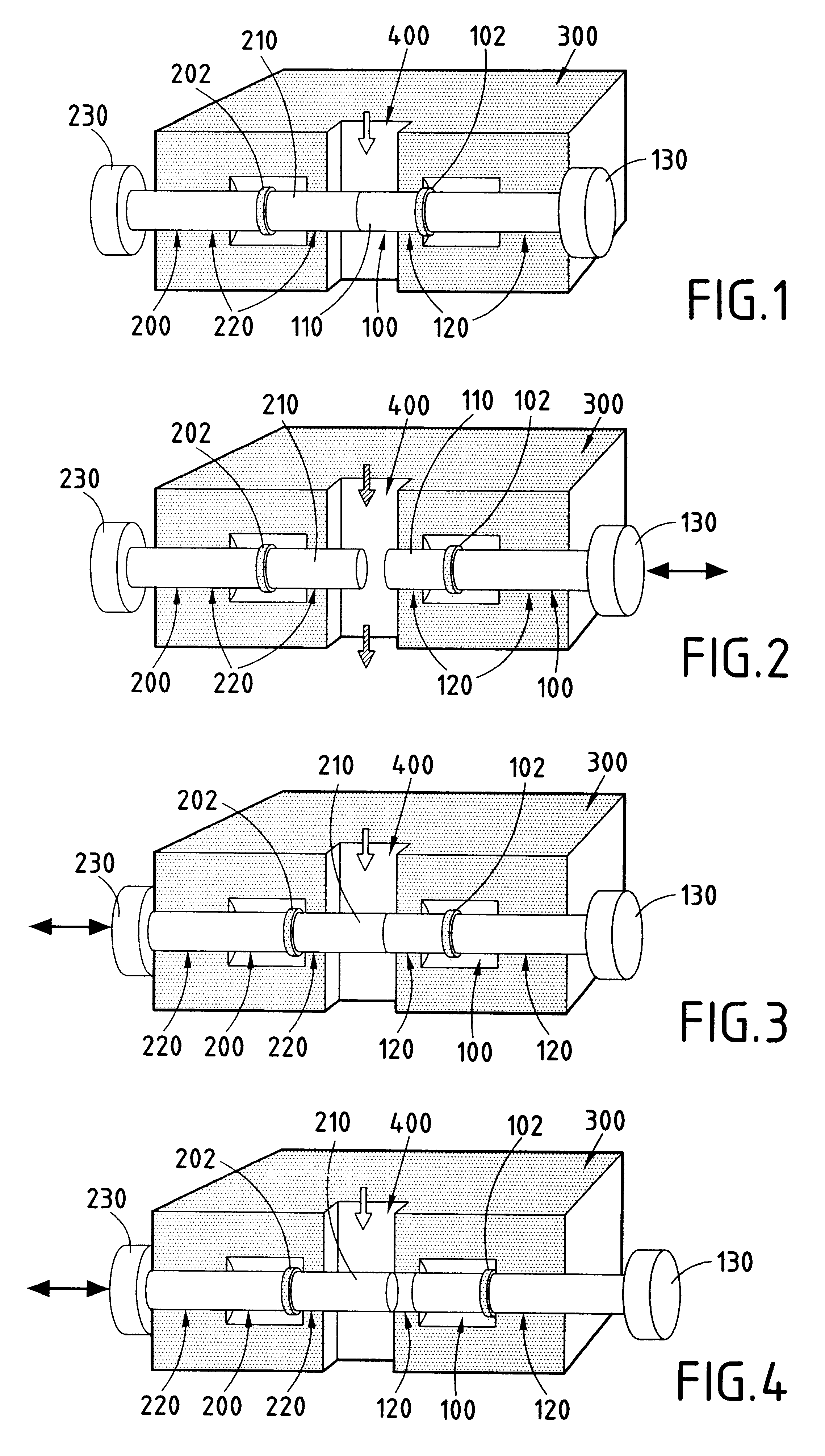
FIG. 10 shows the invention. In FIG. 10, elements analogous to those of the embodiment of FIGS. 7 to 9 are given references corresponding to the last three digits of the corresponding elements described above with reference to FIGS. 7 to 9. The elements 301 to 303 of the valve body 300, interconnected by link means 306 to 309, the main control device 130, and the redundant control device 230, all of which have similar characteristics in FIGS. 7 to 10, are not described again in detail.

The embodiment of FIG. 10 differs in particular by the fact that the main bar 110 and the redundant bar 210 are coaxial and partially engaged one in the other.

More particularly, the main bar 110 comprises a main body 111 with an axial internal channel 113 providing a passage for the flow and opening out radially via openings 113a, 114 through the cylindrical wall of the main bar 110 so as to make it possible when the valve is in its open position for fluid to pass from the inlet orifice 401 of the valv...


PUM


Abstract

The redundant regulation valve for controlling fluid flow comprises a valve body defining a passage for the flow of the fluid, a main throttle element movable by means of a main control device to selectively obstruct the passage, and a redundant throttle element movable by means of a redundant control device. When the valve is in its closed position in normal operation, the main element and the redundant element are in contact with each other. In this normal closed position, the main element is close to its fully-extended position in the closure direction and it obstructs only about half of the passage, while the redundant element is in a position of medium extension. The stroke of the redundant element is such that the redundant element can be controlled to obstruct the entire passage even when the main element is in its fully-open position.

Description

The present invention relates to a redundant regulation valve for controlling the flow of a fluid, the valve comprising a valve body defining a fluid flow passage and a main throttle element movable by means of a main control device to close said passage selectively.PRIOR ARTFIG. 5 is a diagram of a hydraulic installation having full redundancy for controlling selective flow of a fluid in a circuit comprising main pipes 10 and 13. In that redundant system, two parallel pipes 11 and 12 are interposed between the main pipes 10 and 13, and each parallel pipe has interposed therein a series connection of a stop valve 21 (or 22) and a regulation valve 31 (or 32).The circuit shown diagrammatically in FIG. 5 does indeed provide total redundancy by complete duplication of all of the equipment (stop valve and regulation valve), but it suffers from major drawbacks, insofar as the system is bulky, having elements that lead to large mass, thereby making it unsuitable, particularly in space appl...

Claims


Application Information

Patent Timeline
IPC IPC(8): F15B20/00F15B18/00F16K3/24F16K3/00
CPCF15B18/00F15B20/008F16K3/24Y10T137/7761Y10T137/87137Y10T137/87129Y10T137/87917Y10T137/87121
Inventor FOURNIER, JEAN-PIERREMEYER, FRANCISLANGUEDOC, CHRISTIANSALZE, DAVID
Owner SN DETUDE & DE CONSTR DE MOTEURS DAVIATION S N E C M A
Why Eureka
Try Eureka