Method to measure ambient fluid pressure

Inactive Publication Date: 2001-05-01
UNIVERSITY OF PITTSBURGH
View PDF13 Cites 21 Cited by
  • Summary
  • Abstract
  • Description
  • Claims
  • Application Information

AI Technical Summary

Problems solved by technology

Catheters exhibit a finite risk of both morbidity and mortality with routine usage in the clinical situation.
However, this procedure is also invasive with concomitant associations of morbidity and mortality.
There are currently no adequately accurate direct, noninvasive real time clinical methods used to measure pressure in the cardiovascular system.
The indirect approach is filled with errors in difficult cases when good data is most needed and is used only for diagnosing the right side of the heart.
However, it is not known that the precision sized bubbles required for the technical approach have ever been achieved.
Also, at present, it would be nearly impossible to locate bubbles within a specific organ or cavity for the very low concentration of bubbles required by the technology.
A limitation to the technology for usable clinical practice is the inability to control the point of rupture and the lack of precision (Osterle S., Sahines, T., Tucker, C., Tickner, E., et al., The Western Journal of Medicine, 1985 Ott; 143: 463-468.
However, no clinical applications are known to have been developed (Ishihara, K., Kitabatake, A., Tanouchi, J., Fujii, K., Uematsu, M., Yoshida, Y., Kamada, T., Tamura, T., Chihara, K., and Shirae, K., Jpn. J. Appl. Phys., 27(Suppl 27-1): 125-127, 1988) possibly due to

Method used


Image

  • Method to measure ambient fluid pressure
  • Method to measure ambient fluid pressure
  • Method to measure ambient fluid pressure

Examples


example 2

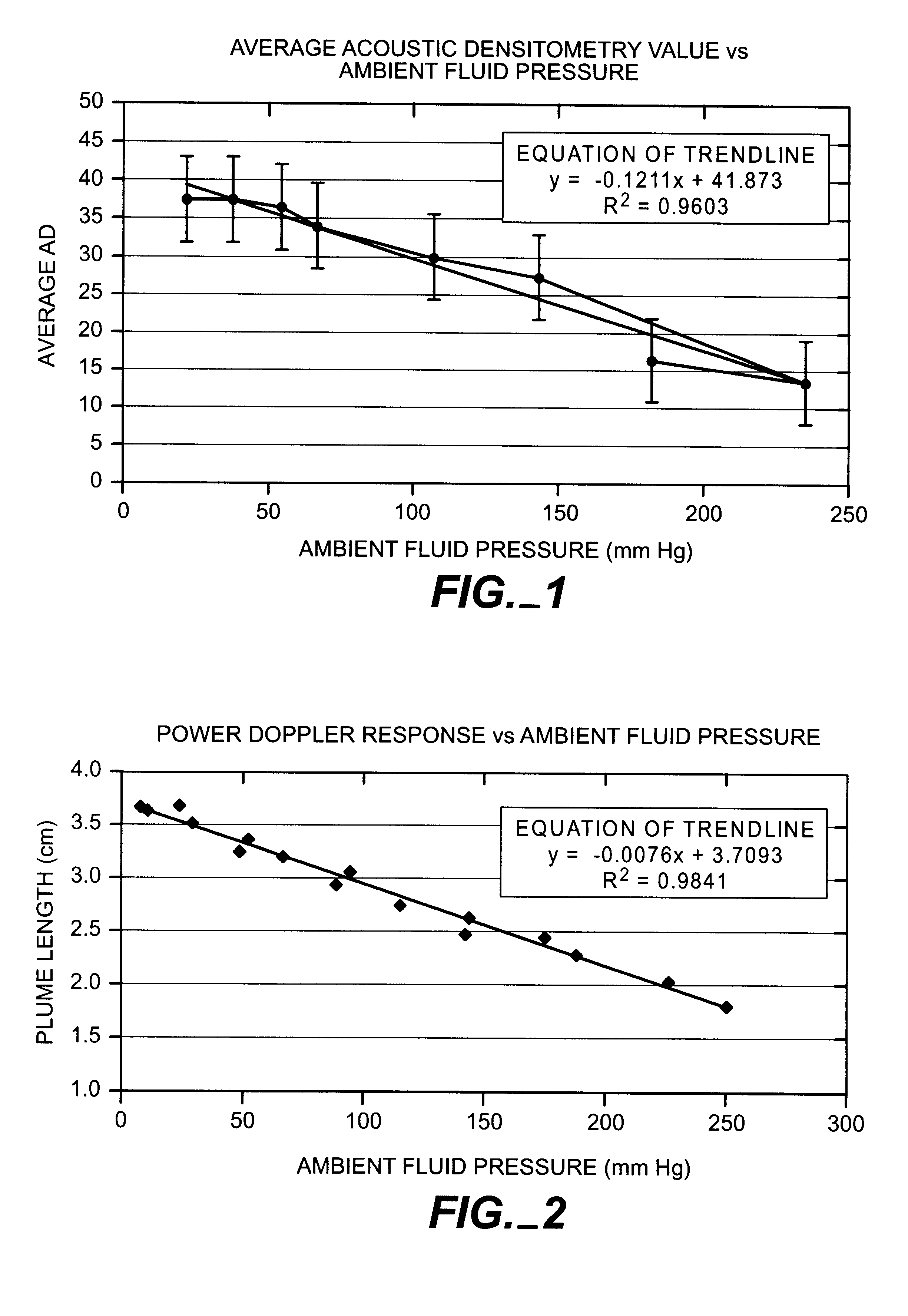
Hewlett Packard SONOS 5500 ultrasound scanner was used in conjunction with a an ATS Laboratories, Model 524 Doppler Flow Phantom. The setup was essentially the same as Example 1. However, the scanner was set up in the Angio (Power Doppler or Doppler decorrelation) mode. In this mode, decorrelation events as determined by Doppler signal processing above a preset threshold are displayed on the monitor of the ultrasound scanner. The flow phantom consists of a housing filled with an elastomer which is designed to mimic the attenuation of living tissue and has four flow channels of 2, 4, 6, & 8 mm diameter respectively running through it. The 6 mm diameter channel of the flow phantom was chosen. The sector scan transducer was oriented along the centerline of the flow tube. When operated in the Angio mode and when microbubbles are present in the flow tube of the phantom, a colored plume derived from the decorrelation events is displayed on the monitor. The plume corresponds to the disrupt...

example 3

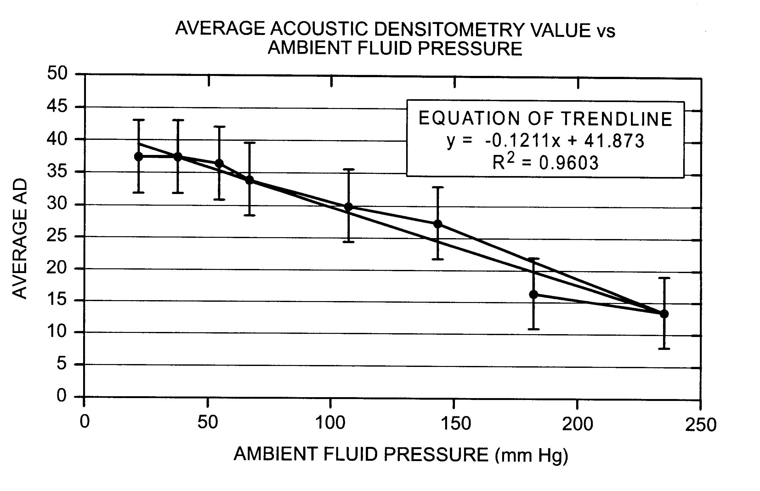
The set-up as presented in Example 2 above was used with the exception that the flow phantom was exchanged for a 6.5 cm diameter by 7.6 cm high acrylic cylindrical phantom chamber with a sealed top and bottom. A magnetic stirring bar was placed in the chamber and the chamber filled completely with de-gassed water. Two ports with luer lock syringe fittings are present to allow connection to the chamber. One port is connected to the pressure transducer, and the other port connected through a 3-way valve to a pressurizing syringe and a sample injection syringe. The S4 transducer of the HP 5500 scanner was placed in a water-filled well on the top of the chamber, imaging directly downward through a thin acrylic cover. The HP SONOS 5500 was run in Angio mode and in B-mode Harmonic. The transducer focus was set at 4 cm in depth, near the mid chamber position. A diluted sample of gas filled, dual walled microbubbles (described in Example 8) was injected into the chamber with the pressure tr...

example 4

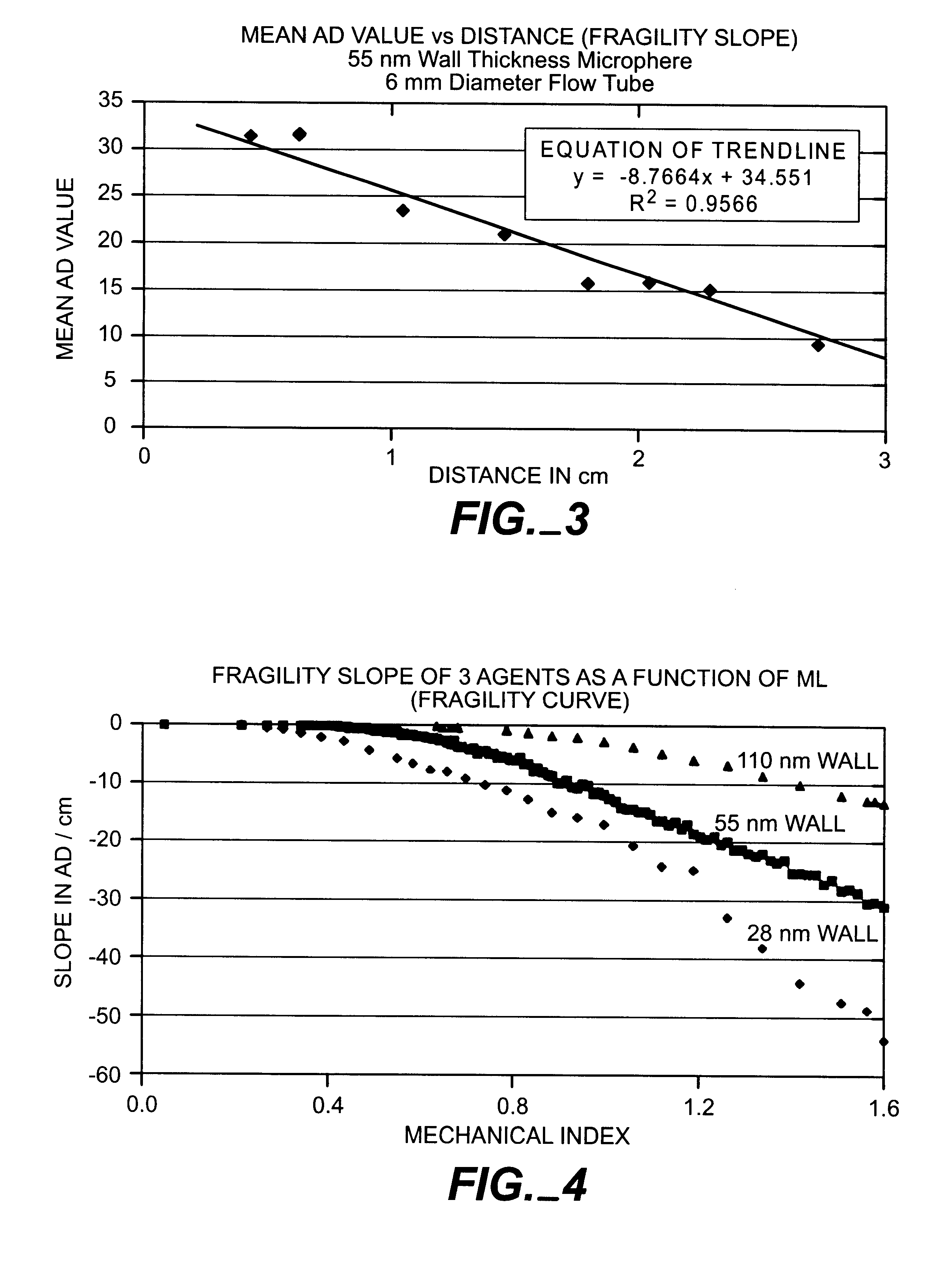
Using the set-up with the HP SONOS 5500 and Doppler Flow Phantom as detailed in Example 2 above, a test was performed to determine the variations in fragility thresholds and their relationship to ambient pressure of microbubbles fabricated with differing wall thickness. Three samples of microbubbles (described in Example 8) were fabricated with polylactide inner walls of thickness approximately 28, 55 and 110 nm respectively. The samples were interrogated using B-mode Harmonic imaging at 1.8 MHz send and 3.6 MHz receive frequencies. Using the AD function, an ROI was placed at the input end of the image of the flow channel and densitometry readings taken at each increment. The ROI was moved laterally, in increments along the flow direction and readings taken. The resultant graph, FIG. 3, shows the exemplary results for one sample (55 nm thickness) as a function of mean AD value versus distance in centimeters along the flow channel. The slope of this line is called the Fragility Slope...


PUM


Abstract

A method is provided for measuring real time ambient pressure at a region of interest in a fluid-filled body cavity by introducing into the cavity a composition of gas-containing microbubbles having a predetermined fragility threshold correlating to the rupture response of their capsules to the ambient fluid pressure and/or applied acoustic pressure. An ultrasonic signal is applied at the region of interest at a power level sufficient to destroy the microbubble population having a fragility threshold below the applied power level. The ultrasound backscatter response is detected from the population of intact and disintegrating microbubbles remaining at the region of interest and this backscatter signal is correlated to predetermined acoustic response properties to determine the ambient pressure at the region of interest.

Description

The present invention relates to a method for measuring real time ambient fluid pressure within a fluid-filled body cavity using gas-filled microbubbles and ultrasonic acoustic energy.BACKGROUND OF INVENTIONTypically, cardiovascular pressures are measured using catheters which are introduced into the vascular systems via an artery or vein. Catheters exhibit a finite risk of both morbidity and mortality with routine usage in the clinical situation. More recently, sensor tipped guidewires to measure pressure have been developed. However, this procedure is also invasive with concomitant associations of morbidity and mortality. There are currently no adequately accurate direct, noninvasive real time clinical methods used to measure pressure in the cardiovascular system. An indirect method exists using Doppler ultrasound as suggested by Laaban, et al. (Laaban, J., Diebold, B., Zelinski, R., Lafay, M., Raffoul, H., and Rochemaure, J., Chest 96, (6): 1258-1262, 1989). With Doppler techniqu...

Claims


Application Information

Patent Timeline
IPC IPC(8): A61B8/00A61B8/04
CPCA61B8/04A61B8/481
Inventor TICKNER, E. GLENNCONSTON, STANLEY R.
Owner UNIVERSITY OF PITTSBURGH
Why Eureka
Try Eureka