Method for the transmission of reference signals in an OFDM system

Inactive Publication Date: 2001-05-01
DEUTSCHE THOMSON-BRANDT GMBH
View PDF11 Cites 122 Cited by
  • Summary
  • Abstract
  • Description
  • Claims
  • Application Information

AI Technical Summary

Problems solved by technology

One of the main problems connected with such systems is synchronization when a receiver is switched on or tuned t

Method used


Image

  • Method for the transmission of reference signals in an OFDM system
  • Method for the transmission of reference signals in an OFDM system
  • Method for the transmission of reference signals in an OFDM system

Examples


Embodiment Construction

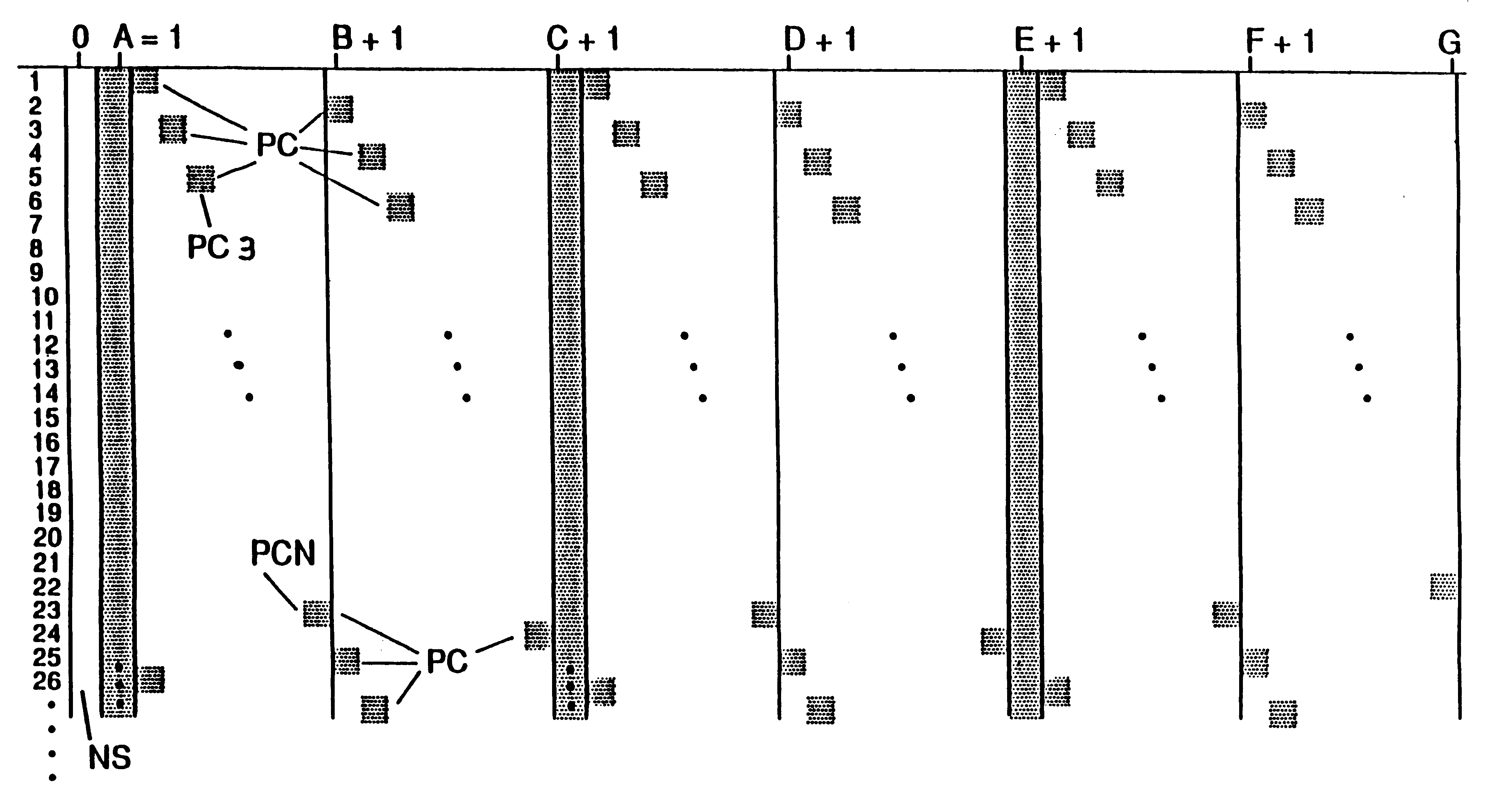
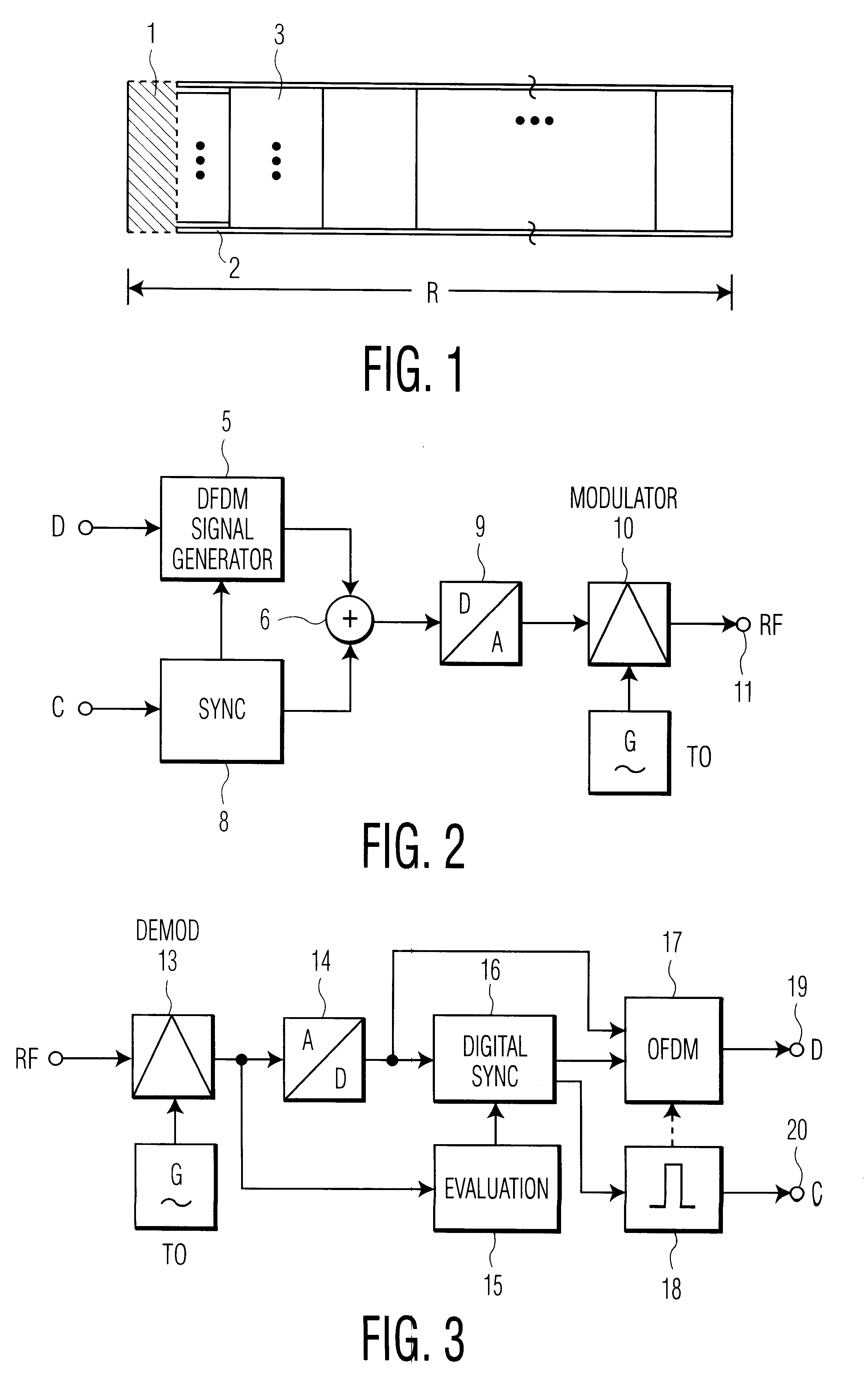
In FIG. 1, the entire frame R first of all contains the hatched component 1 with 0 or approximately 0 power, then the signal component 2 of the synchronization symbol with the modulation which differs from the useful signal, 1+2 constituting the entire sync symbol. There then follows the section 3 with the OFDM symbols for the useful data.

In the OFDM signal generator 5 of FIG. 2, an OFDM baseband signal is generated with the aid of the useful data stream D (for example television video data). In the sync stage 8, the synchronization symbol, comprising the zero components and the signal component (sequence), is generated in baseband from the clock signal C. The synchronism between the signals of the stages 5 and 8 is established in that a clock and window signal originating in the stage 8 controls the signal timing in the stage 5. The two baseband signal components which are generated are combined in the adder stage 6. The output signal of the adder stage 6, containing the OFDM signa...


PUM


Abstract

A method and device in which only a single symbol is required for synchronization, and which permits the detection of appreciable deviations from the normal receiver oscillator frequency or of a deviation of the transmitter frequency from the given frequency pattern, and the correction of the oscillator frequency. The invention further includes an evaluation method for the signal which contains a multiplicity of modulated carriers. In a decoder, additional sequences are evaluated after demodulation and differential reconversion by means of a correlation.

Description

The invention relates to a method for digital signal transmission in frames using a multiplicity of modulated carriers, to corresponding evaluation methods for this signal and to a corresponding device for decoding.Prior ArtVarious methods for terrestrial transmission of digital broadcast signals are known, such as OFDM, QPSK and QAM modulation. One of the main problems connected with such systems is synchronization when a receiver is switched on or tuned to another channel.A synchronization method of this type for DAB (Digital Audio Broadcasting) is known, in which a complete zero symbol and a so-called TFPC (Time Frequency Phase Control) symbol are successively transmitted and are evaluated in a specific manner in the receiver. In the same way as the signal currents of the useful information to be transmitted, the TFPC symbol is assigned to the individual carriers or frequencies of the OFDM multi-carrier method. For the purpose of evaluation, the samples are transformed into a fre...

Claims


Application Information

Patent Timeline
IPC IPC(8): H04L27/26H04L27/34H04J11/00H04L5/06H04L7/00H04L27/18
CPCH04L5/0048H04L27/2613H04L27/2659H04L27/266H04L27/2675H04L5/0007H04L27/2663H04L27/2665H04L27/26136
Inventor KLANK, OTTOLAABS, JURGEN
Owner DEUTSCHE THOMSON-BRANDT GMBH
Why Eureka
Try Eureka