Bolometric heat detector

a heat detector and bolometric technology, applied in the field of bolometric heat detectors and bolometric detection devices, can solve the problems of incompatible heat treatment at high temperature, poor resistive contact with doped semiconductors, and relatively high cost of techniques

Inactive Publication Date: 2001-05-08
COMMISSARIAT A LENERGIE ATOMIQUE ET AUX ENERGIES ALTERNATIVES
View PDF8 Cites 36 Cited by
  • Summary
  • Abstract
  • Description
  • Claims
  • Application Information

AI Technical Summary

Benefits of technology

will become more evident after reading the following description. This description concerns example embodiments that are given for explanatory purpose and are in no way restrictive, with reference to the attached drawings in which:

Problems solved by technology

For this type of device, there is a problem in obtaining a good resistive contact with the doped semiconductor.
These techniques are firstly relatively expensive to use, and secondly require heat treatments at high temperature incompatible with a bolometric technology assembled on a CMOS or CCD type silicon multiplexing circuit.
However, this technique is very difficult to use due to the lack of selectivity between the two layers, and since their thicknesses are very small.

Method used


Image

  • Bolometric heat detector
  • Bolometric heat detector
  • Bolometric heat detector

Examples


Embodiment Construction

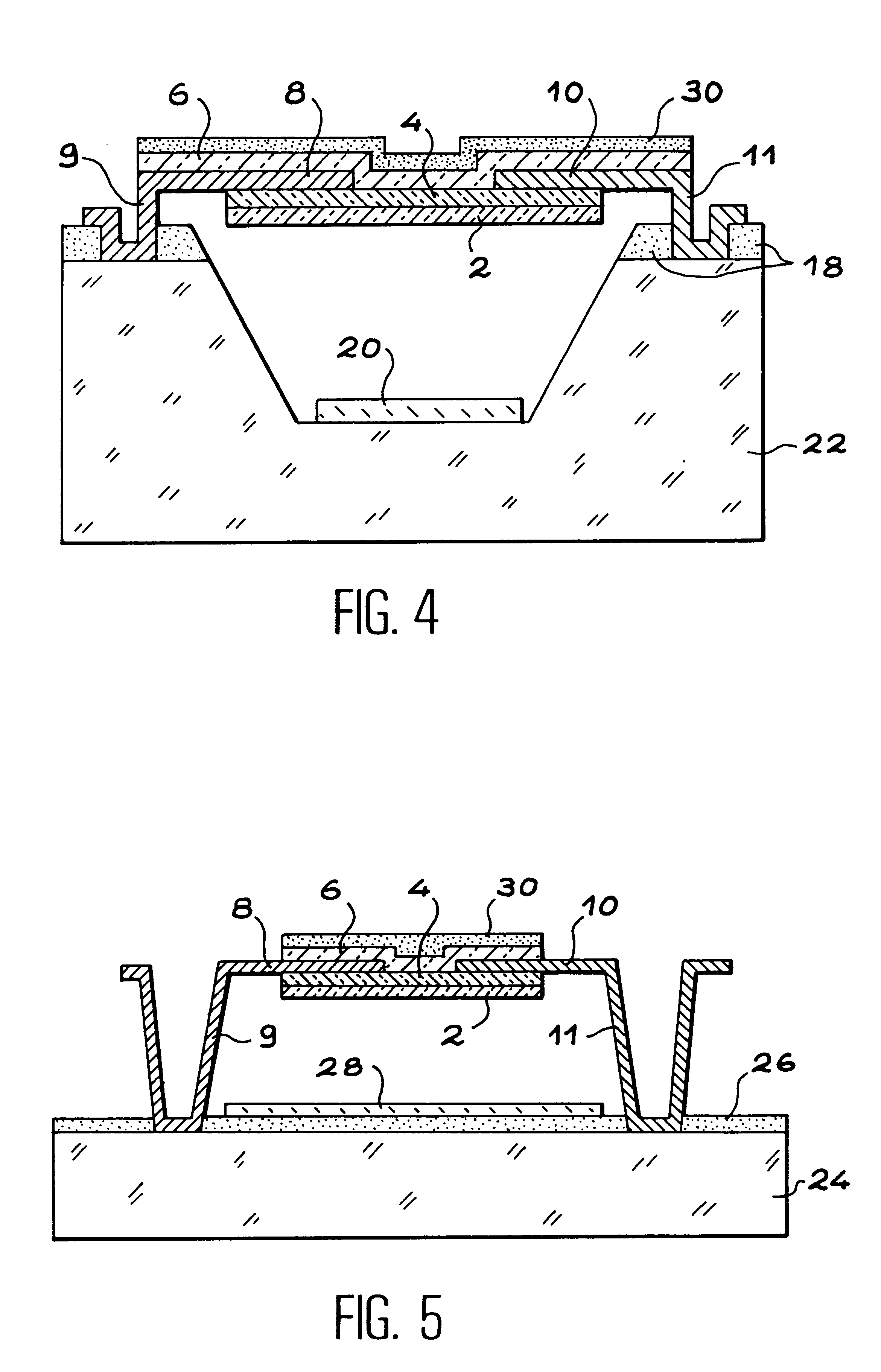
The purpose of the invention is a bolometric heat detector and a bolometric detection device with a good resistive contact and a good temperature coefficient (TCR).

Another purpose of the invention is to make a imple low cost bolometric type detection structure that guarantees very good resistive contacts and therefore generates very little low frequency noise.

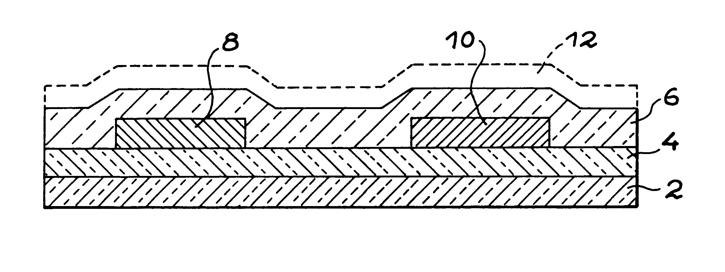
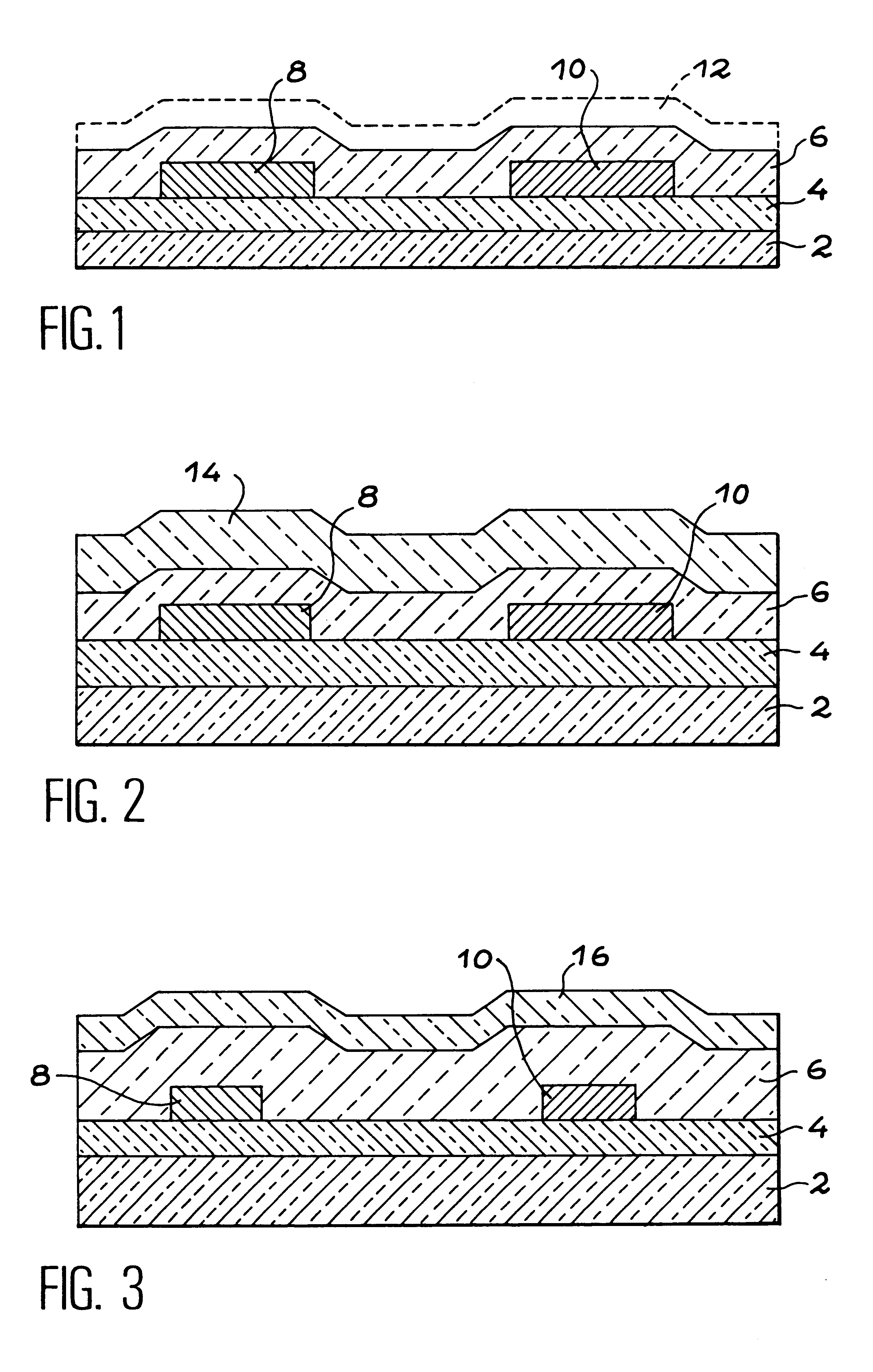
In order to maintain good resistive contact and a good TCR, the invention proposes to depopulate carriers in the inter-electrodes area by using a semiconducting doping layer of the type opposed to that used in the inter-electrodes layer.

Therefore the bolometric heat sensor or detector according to the invention includes an active part composed of at least two coplanar electrodes in electrical contact with a first thin semiconducting layer doped by a first doping agent with a first type of conductivity, a second thin semiconducting layer doped like the first layer, or undoped, in electrical contact with the electrodes, and a thi...


PUM


Abstract

A bolometric heat detector having an active part composed of at least two coplanar electrodes (8, 10) placed in electrical contact with a first thin semiconducting layer (6), doped by a first doping agent with a first type of conductivity. There is a second thin semiconducting layer (4) doped like the first layer or undoped, and a third thin semiconducting layer (2) doped by a second doping agent with a second type of conductivity opposed to the first. The second layer (4) is placed between the first (6) and the third (2) layers.

Description

TECHNICAL DOMAIN AND PRIOR ARTThe invention relates to bolometric heat detectors, for example to detect infrared and / or nuclear radiation (X-rays, .gamma. rays, neutrons, etc.)Infrared detectors usually comprise a sensitive element that can be heated by infrared radiation in band III (8 to 12 .mu.m), characteristic of the temperature and emissivity of observed bodies. The temperature increase in the sensitive element causes a variation in an electrical property of the sensitive material; electrical charges appear by the pyro-electric effects, or a capacitance variation due to a change in the dielectric constant, or a variation in the resistance of a semiconducting or metallic material.These detectors usually operate at high performance as a result of a low calorific mass of the sensitive material, good thermal insulation between the active layer and its support (these first two conditions require the use of thin layers) and finally high sensitivity of the conversion effect from a te...

Claims


Application Information

Patent Timeline
Patent Type & Authority Patents(United States)
IPC IPC(8): G01J5/20H01L31/09H01L31/08
CPCG01J5/20H01L31/09
Inventor OUVRIER-BUFFET, JEAN-LOUISYON, JEAN-JACQUES
Owner COMMISSARIAT A LENERGIE ATOMIQUE ET AUX ENERGIES ALTERNATIVES
Why Eureka
Try Eureka