Core for a controllable inductor and a method for producing therof

a controllable inductor and core technology, applied in the direction of transformer/inductance details, variable inductance, inductance, etc., can solve the problems of magnetic flux, inability to meet the requirements of several and expensive fixtures, and failure to meet the requirements of the controllable inductor

Inactive Publication Date: 2001-05-15
ABB (SCHWEIZ) AG
View PDF6 Cites 23 Cited by
  • Summary
  • Abstract
  • Description
  • Claims
  • Application Information

AI Technical Summary

Problems solved by technology

The core rings have thereafter been given a rigid form, usually by a vacuum pressure impregnation, producing one core at a time and thereby requiring several and expensive fixtures, usually a single fixture for each core ring, to get the rings circular and plane, which has not always been successful.
Because of that some of these core rings have become somewhat obliquely while being cured, the gap between two successive rings might thereafter become uneven and on some places too big, which results in that at the latter use of the core in the controllable inductor the resistance against the magnetic flux will become larger at these places, causing the flux lines to run obliquely out into the air, which in turn results in oblique directions of the magnetic flux and increased eddy current losses in the core.
A further disadvantage with this known production technique is that the cores resulting from this technique will become relatively fragile for impacts and delicate to transport.

Method used


Image

  • Core for a controllable inductor and a method for producing therof
  • Core for a controllable inductor and a method for producing therof
  • Core for a controllable inductor and a method for producing therof

Examples


Embodiment Construction

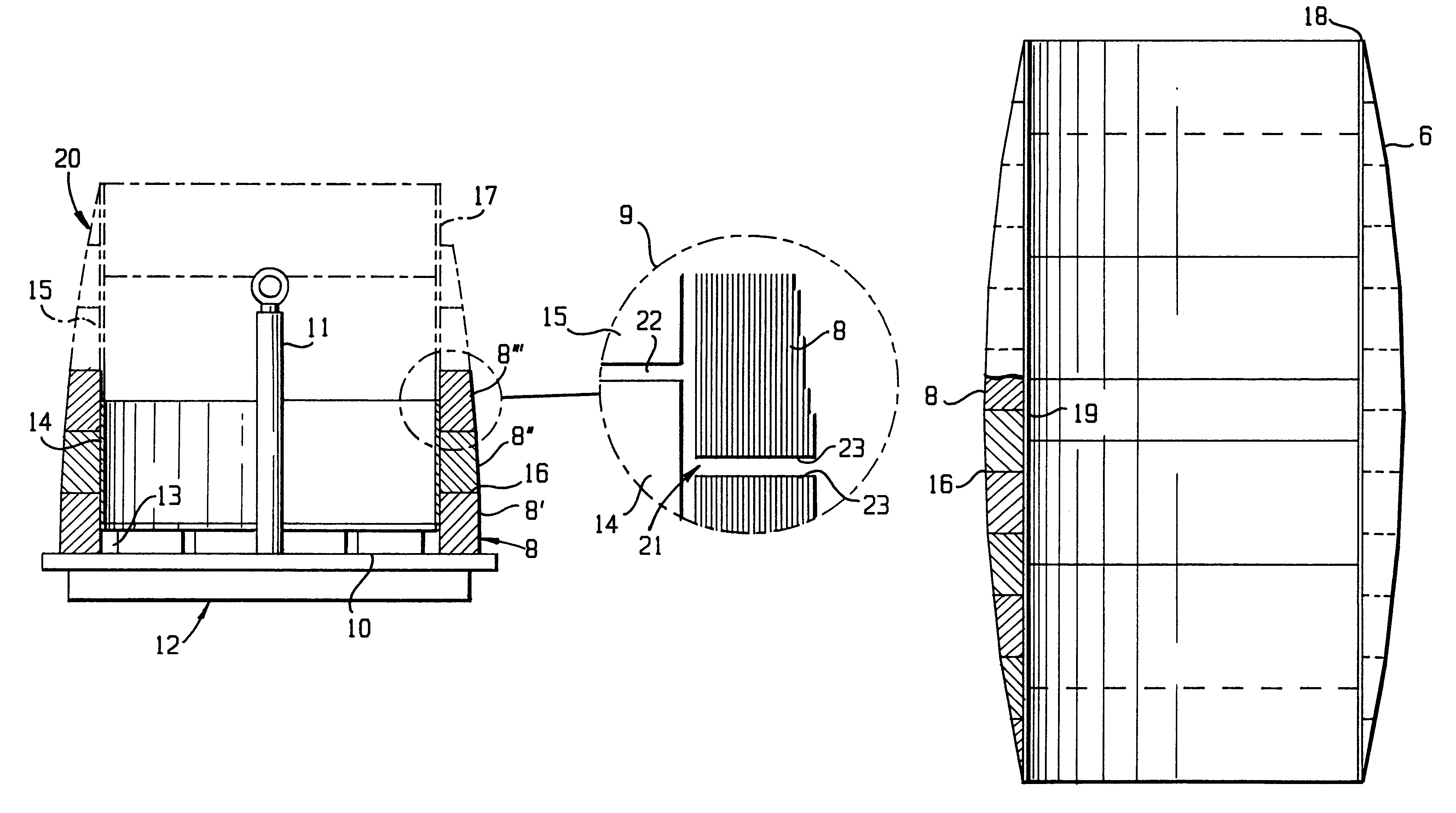
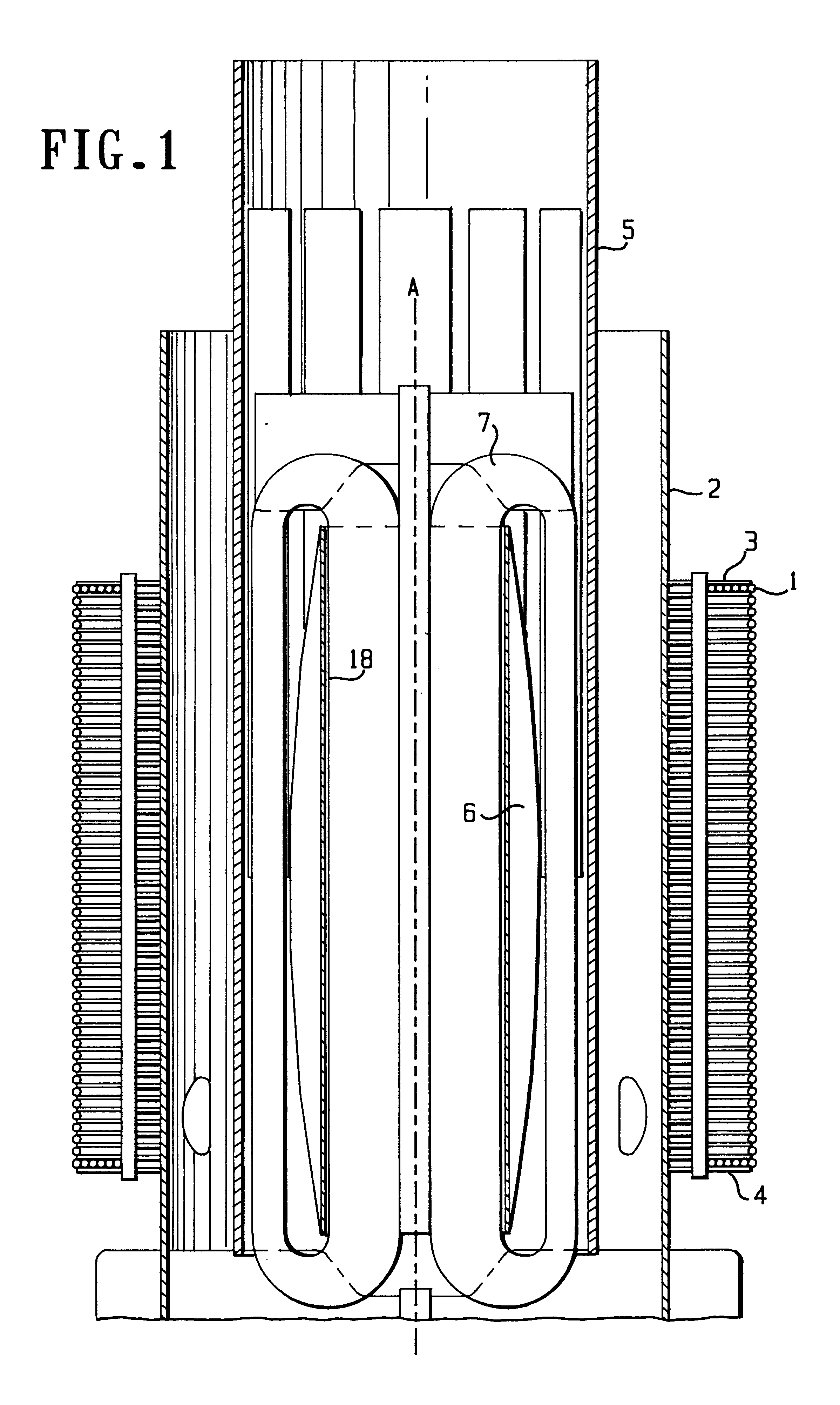
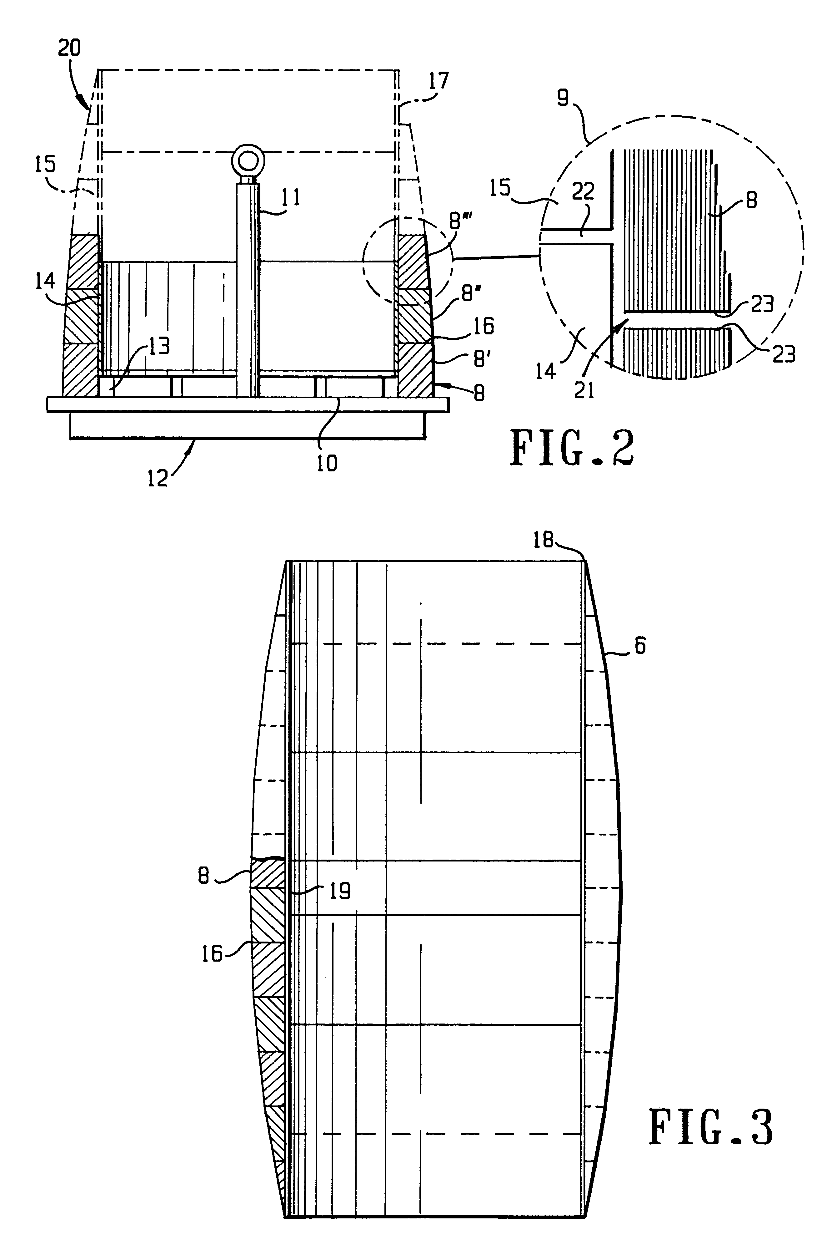
The general construction of a controllable inductor, in which a tubular core according to the invention is intended to be utilized, is illustrated in FIG. 1. This controllable inductor has the following general construction. It has a main winding 1 intended to be connected to a high voltage net and which main winding is wound in layers at a distance outside a cylinder 2 of electrically insulating material. The main winding 1 has one end 3 being on the same voltage potential as the high voltage net, said voltage dropping in direction towards the opposite lower end 4 in FIG. 2, said end 4 being on ground potential. A cylinder 5 of electrically insulating material is arranged inside and running coaxially to the cylinder 2. In the room defined by the cylinder 5 a core 6 is located and running co-axially against the same, the construction and method for production of said core being object for the present invention and which core having a partly conical form at its ends, which form is to...


PUM

PropertyMeasurementUnit
thicknessaaaaaaaaaa
thicknessaaaaaaaaaa
inner diameteraaaaaaaaaa

Abstract

A tubular core (6) for a controllable inductor with a main winding (1) surrounding the core and a control winding (7) passing substantially axially through the core. The core (6) is capable of receiving a magnetic flux from the main winding (1) running substantially axially therethrough and having a plurality of core rings (8) stacked co-axially on top of each other and connected to a rigid unit. The core rings (8) are connected to each other forming a walled construction. The core (6) also has an inner envelope (18) with an outer cross-section that is substantially equal to the inner cross-section of the core ring walled construction. The walled construction has joints (16) between the core rings (8) in an axial direction which are overlapped by a part of the envelope (18).

Description

FIELD OF THE INVENTION AND PRIOR ARTThe present invention relates to a tubular core for a controllable inductor with a main winding surrounding the core and a control winding passing substantially axially through said core, said core being intended to receive a magnetic flux from said main winding running substantially axially therethrough and comprising a number of core rings stacked co-axially on top of each other and connected to a rigid unit.Such a controllable inductor is previously known from for example the applicant's WO 94 / 11891. The definition of "controllable" is to be given such a wide meaning, that it also comprises the case that a control current which is constant over time passes through the control winding.A controllable inductor of this type functions in conjunction with a capacitor as a so-called harmonic filter in connection with a high voltage station for converting direct voltage to alternating voltage, wherein its main winding is connected to the high voltage n...

Claims


Application Information

Patent Timeline
Patent Type & Authority Patents(United States)
IPC IPC(8): H01F29/00H01F29/14H01F27/26H01F41/02
CPCH01F27/263H01F29/146H01F2029/143
Inventor ZINDERS, GUNNARHOLMGREN, TOMMYSANDIN, BJORNVALDEMARSSON, STEFANELOFSSON, DANEKWALL, OLLE
Owner ABB (SCHWEIZ) AG
Why Eureka
Try Eureka