Airbag inflator and an airbag apparatus

a technology of airbag inflator and airbag, which is applied in the directions of pedestrian/occupant safety arrangement, vehicular safety arrangement, separation process, etc., can solve the problems of relatively high burn relatively high combustion rate and undesirable toxicity level, and it is practically impossible to manufacture gas generating material in the form of pellets or disks. , to achieve the effect of excellent arresting capability, excellent corrosion resistance and complex clearance structur

Inactive Publication Date: 2001-05-22
DAICEL CHEM IND LTD
View PDF64 Cites 64 Cited by
  • Summary
  • Abstract
  • Description
  • Claims
  • Application Information

AI Technical Summary

Benefits of technology

The coolant / filter is preferably made by stacking the flat-plaited metal meshes in the radial direction and then compressing them in the radial and axial directions. The coolant / filter thus formed has a complex clearance structure and thus an excellent arresting capability. In this way, an integrated coolant / filter having both the cooling function and the arresting function is realized. In a preferred embodiment, such a coolant / filter has a pressure loss of 0.3.times.10.sup.-2 to 1.5.times.10.sup.-2 kg / cm.sup.2 under the conditions of a normal temperature and a flow rate of 100 l / min / cm.sup.2.
In more concrete terms, the steps of making the coolant / filter involves forming a flat-plaited stainless steel mesh into a cylinder, repetitively folding one end portion of the cylinder outwardly to form an annular multi-layer body, and compressing the multi-layer body in a die. Alternatively, the coolant / filter may be made by forming a flat-plaited stainless steel mesh into a cylinder, pressing the cylinder in the radial direction to form a plate member, rolling the plate member into a multi-layer cylinder body, and compressing the multi-layer cylinder body in a die. The stainless steels used for the meshes include SUS304, SUS310S, and SUS316 (JIS Standard). SUS304 (18Cr-8Ni-0.06C), an austenite stainless steel, exhibits an excellent corrosion resistance.
The coolant / filter may also be formed in a double layer structure having a mesh with a wire diameter of 0.3 to 0.5 mm and, on the inner side of the mesh, a layer 1.5 to 2.0 mm thick of a mesh with a wire diameter of 0.5 to 0.6 mm. The inner mesh layer has a coolant / filter protection function, i.e., protecting the coolant / filter against the flames from the ignition material ejected toward the coolant / filter and against the combustion gas produced when the gas generating material is ignited and burned by the flames.

Problems solved by technology

Conventional airbag inflators are relatively complex structures with such as forged housings defining internal ignition, combustion, and filter chambers by integrally formed and / or welded internal partitions.
Many such conventional inflators use azide based gas generating materials such as sodium azide based materials which have relatively high burn rates and undesirable toxicity levels and products of combustion such as mists and ash associated therewith.
Thus, it is practically impossible to manufacture the gas generating material in the form of pellets or disks that are industrially stable and can withstand many hours of vibrations of an automobile.
It has been difficult to develop the airbag inflator that meets the desired performances.
Forged products, though they are homogeneous in the metal structure and highly tenacious, have a drawback of high cost.
When the shell members having many concentric cylinders as disclosed in the above U.S. patent are manufactured by forging, the circular portion 46 is not flat and requires a cutting work, increasing the number of manufacturing processes and therefore cost.
Changing the volume of the cylinder 43 therefore is not easy.
In the above conventional airbag inflator, because the coolant / filter chamber is formed outside the combustion chamber, the diameter of the airbag inflator becomes large, increasing its size and weight.
Further, because the combustion chamber is defined by the cylinder 44 of the diffuser shell, the diffuser shell is complex in shape, making the manufacture of the airbag inflator difficult and increasing the cost.
The conventional coolant still has a problem from the standpoint of effectively entrapping fine combustion particulates because of its simple clearance structure.
Moreover, the conventional coolant has a small pressure loss (has a good gas permeability), which makes it difficult to define a pressure chamber such as combustion chamber.
Therefore, the airbag inflator equipped with the conventional coolant uses an increased number of parts, and has an increased diameter resulting in an increase in the size and weight.
Furthermore, the conventional coolant having a small bulk density (a value obtained by dividing a mass of the molded article by a bulk volume thereof) is not capable of defining a pressure chamber, has a small shape-retaining strength and is, hence, deformed upon the application of a gas pressure, adversely affecting the entrapping of combustion particulates.

Method used


Image

  • Airbag inflator and an airbag apparatus
  • Airbag inflator and an airbag apparatus
  • Airbag inflator and an airbag apparatus

Examples


second embodiment

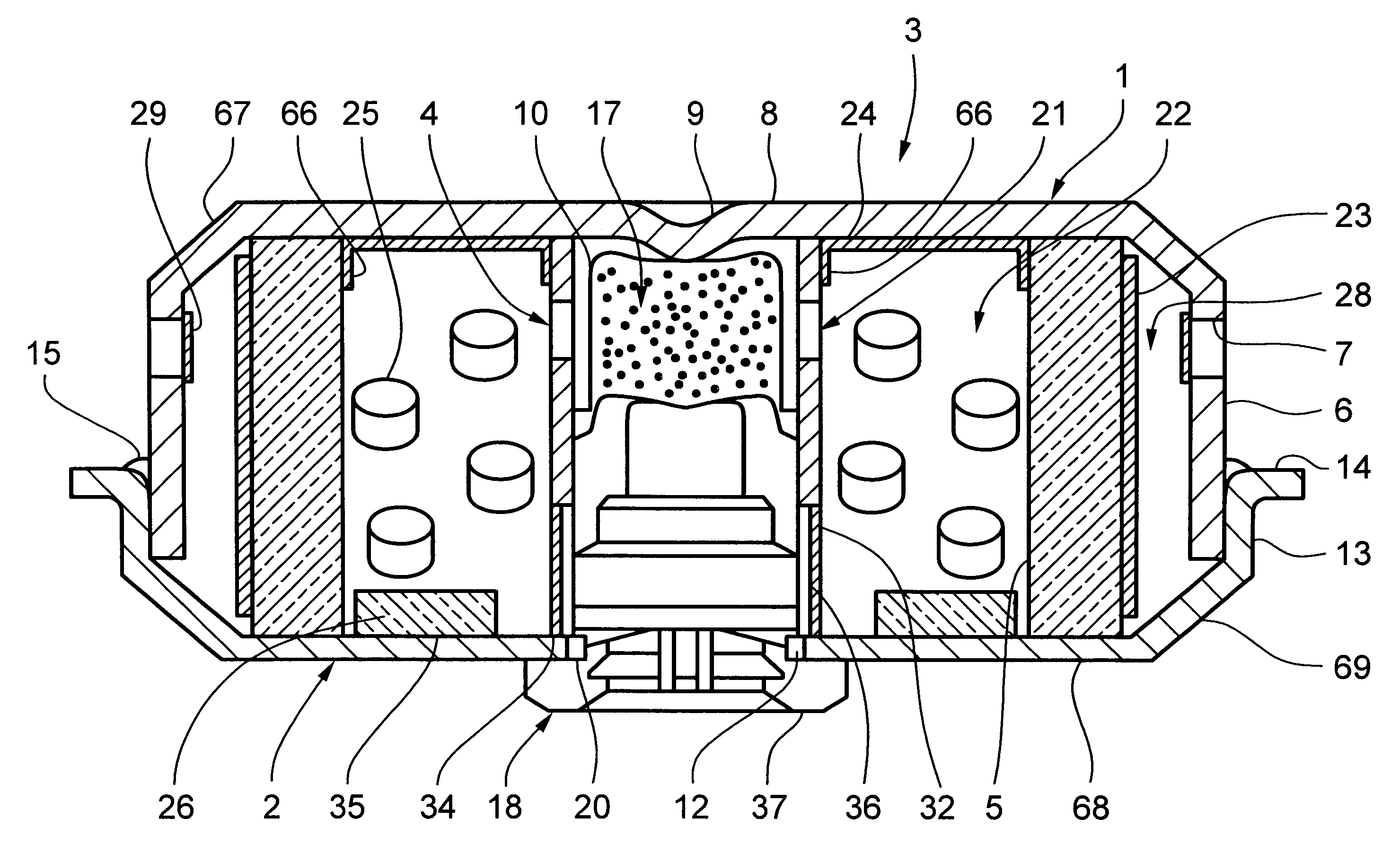
The coolant / filter 5' has a coolant / filter support member 38 that blocks the displacement of the coolant / filter 5'. The coolant / filter support member 38 is made by pressing a stainless steel plate about 1 mm thick and has an annular portion 39, which surrounds the horizontally outwardly projecting flange 33 and engages with the inclined portion 70, and a flame resisting plate portion 60 bent from the annular portion 39. The flame resisting plate portion 60 is disposed facing the row of through-holes 21' which are formed in the central cylinder member for the passage of flames from the ignition means and covers an inner circumferential surface 61 of the coolant / filter 5. The flame resisting plate portion 60 has a function of protecting the coolant / filter 5' against flames ejected toward it and also a function of changing the direction of the ejecting flames to ensure that the flames reach the far side of the gas generating material 25' to facilitate combustion. In addition to the inc...

embodiment 2

In the embodiment 1 and embodiment 2, the gas generating material was ignited by the igniter without using a transfer charge.

In the comparison case 1, the gas generating material failed to be ignited without a transfer charge because the decomposition initiation temperature is high and the combustion temperature is too low.

In the comparison case 2, the gas generating material failed to be ignited without a transfer charge because the combustion temperature is low although the decomposition initiation temperature is low.

There is a desire to limit the amount of combustion particulates discharged with the gas from the discharge (diffuser) ports of the inflator housings because such particulates tend to burn an airbag attached to the inflator. An optimum range of particulates is not to exceed 2 g. It should be noted that the combustion temperature of the gas, per se, is not a critical factor for preventing airbag damage.

The coolant / filters of the present invention must work such that th...


PUM

PropertyMeasurementUnit
equivalent circle diameteraaaaaaaaaa
thicknessaaaaaaaaaa
internal volumeaaaaaaaaaa

Abstract

An airbag inflator includes non-azide gas generating propellants, surrounding an ignition device, disposed inside a housing. The gas generating propellants are surrounded by a coolant/filter device having a pressure loss of 0.3x10⁻² to 1.5x10⁻² kg/cm2 at a flow rate of 100 l/min/cm2. A space is provided between an outer periphery of the coolant/filter device and the housing such that the combustion gas passes through the entire area of the coolant/filter device. The coolant/filter device is also surrounded by a swell suppressing layer which prevents the coolant/filter device from swelling due to a combustion of the gas generating propellants.

Description

This invention relates to airbag inflators and systems utilizing same for the enhancement of driver and passenger protection, including side impact protection, in motor vehicles and the like.Conventional airbag inflators are relatively complex structures with such as forged housings defining internal ignition, combustion, and filter chambers by integrally formed and / or welded internal partitions. Furthermore, coolant structures, such as filters formed from heat conductive materials and the like, in many cases require the foregoing structural complexities in order to withstand the temperatures and pressures generated within these inflator structures.Many such conventional inflators use azide based gas generating materials such as sodium azide based materials which have relatively high burn rates and undesirable toxicity levels and products of combustion such as mists and ash associated therewith.Accordingly, there is a need in the prior art for more simplistic inflator structures, su...

Claims


Application Information

Patent Timeline
Patent Type & Authority Patents(United States)
IPC IPC(8): B01D46/24B60R21/26B60R21/16C06D5/00C06D5/06B60R21/20B60R21/203B60R21/264B60R21/33
CPCB01D46/2411B01D46/4263B60R21/2644B60R21/33C06D5/06B01D2275/105B01D2279/10B60R21/2035B60R21/261B60R2021/26017
Inventor KATSUDA, NOBUYUKIODA, SHINGOUEDA, MASAYUKI
Owner DAICEL CHEM IND LTD
Why Eureka
Try Eureka