Method of repairing a thermal barrier coating

a thermal barrier and coating technology, applied in the direction of coatings, foil printing, liquid/solution decomposition chemical coatings, etc., can solve the problems of thermal barrier localization, inability to adapt to field repair of components, and possible thermal barrier palllation

Inactive Publication Date: 2001-05-22
SOUTHWEST RES INST
View PDF20 Cites 51 Cited by
  • Summary
  • Abstract
  • Description
  • Claims
  • Application Information

AI Technical Summary

Benefits of technology

It is another object of the present invention to provide a method for field repair of a thermal barrier coating on a component which does not require the removal of the component.

Problems solved by technology

Under the severe environmental conditions in which the engine components operate, spallation may occur in localized regions of the thermal barrier coating during engine operation.
This prior art technique requires special equipment for applying the coating and is not easily adaptable to field repair of the components.

Method used


Image

  • Method of repairing a thermal barrier coating
  • Method of repairing a thermal barrier coating

Examples


Embodiment Construction

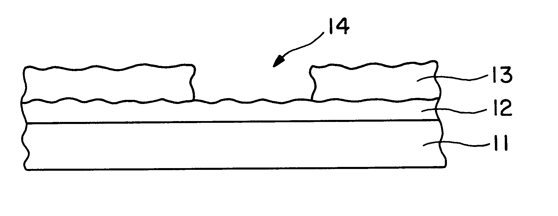
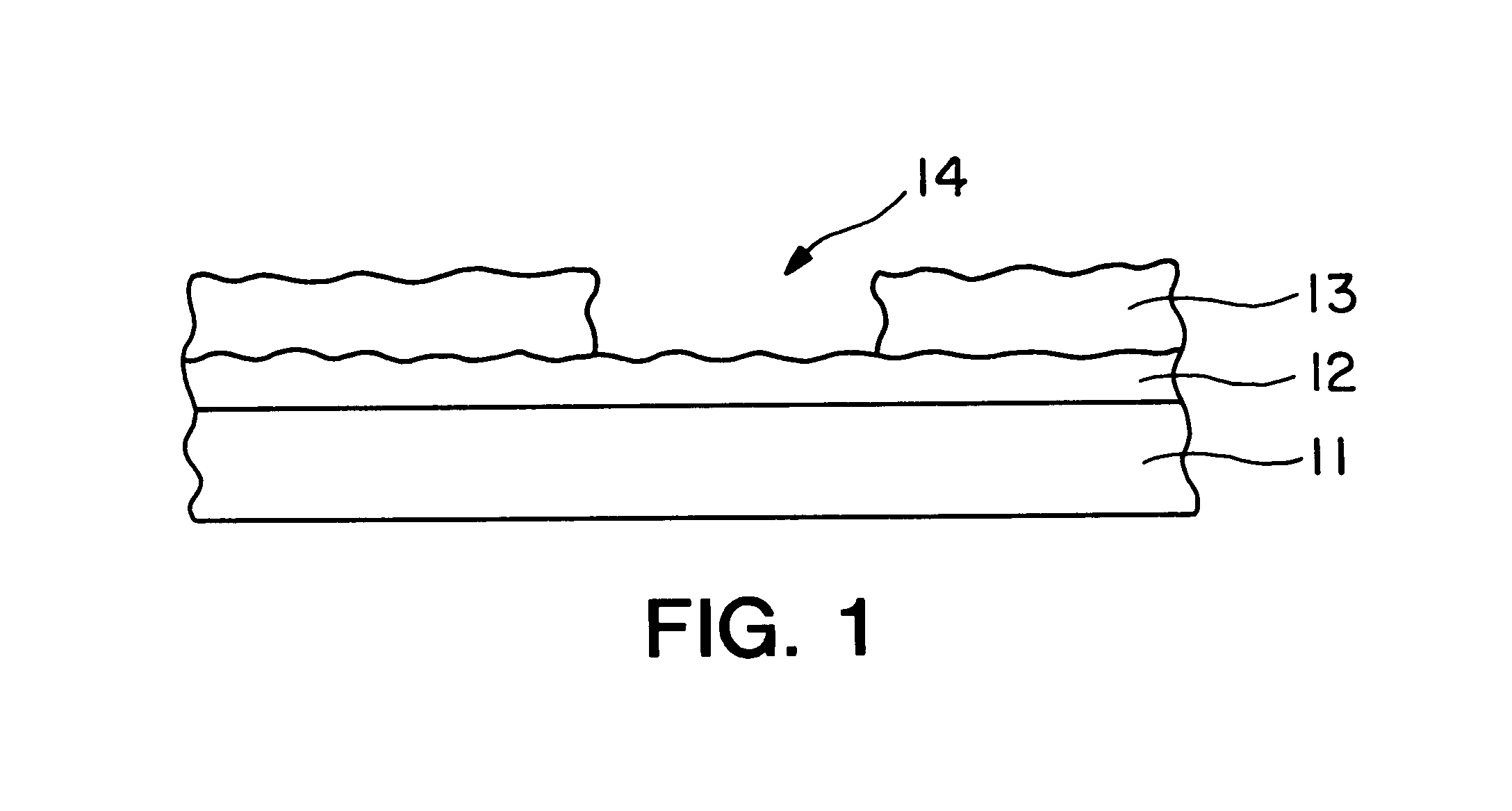
Referring to FIG. 1, a cross section of a portion of a component 11 is shown with a suitable metallic bond layer 12 and a thermal barrier coating 13. The area 14 indicates damage or spallation of the thermal barrier coating, which typically is from 75 to about 300 micrometers in thickness. Typically, the damage only extends partially through the thermal barrier coating; however, the present method of repair also could be used to repair damage which extended completely through the thermal barrier coating to the bondcoat.

In accordance with the present invention, the damaged area is cleaned to remove any oxides or fragments of the ceramic thermal barrier coating to expose the metallic bond layer 12. The damaged area 14 is repaired by applying a sol-gel of partially stabilized zirconia (PSZ). After the sol-gel is applied to the damaged area and the solvent allowed to evaporate leaving the PSZ precursor. This process can be repeated until a precursor of suitable thickness is achieved. Th...


PUM

PropertyMeasurementUnit
thicknessaaaaaaaaaa
shrinkageaaaaaaaaaa
diameteraaaaaaaaaa

Abstract

A method of repairing a damaged area of a thermal barrier coating on a component which is subjected to a hostile thermal environment, which comprises cleaning the damaged area, applying a partially stabilized zirconium sol-gel to the area, and pyrolizing the sol-gel to form a TBC repair layer.

Description

The present invention relates to the repair of stabilized zirconia thermal barrier coatings that have suffered localized spallation in the hostile thermal environment to which the coating has been exposed.Higher operating temperatures are sought to increase the efficiency of internal combustion engines and gas turbine engines. To this end, the surfaces of the engine components subjected to the high temperatures have been provided with thermal barrier coatings to increase their durability under the high temperature operating conditions, which may include cyclic temperature and compression loads.The thermal barrier coatings must have a low thermal conductivity and adhere to the alloy material of the component. Generally, the surface of the component is provided with a thin metallic bond layer to protect the alloy metal component from the corrosive environment to which it is subjected.Typical metallic bond layers or coatings are an oxidation resistant alloy such as MCr-AlY where M is i...

Claims


Application Information

Patent Timeline
Patent Type & Authority Patents(United States)
IPC IPC(8): C23C24/00C23C18/00C23C24/08C23C4/02C23C18/12
CPCC23C4/02C23C18/1204C23C18/1225C23C18/1254C23C24/08
Inventor LEVERANT, GERALD R.SCHWAB, STUART T.PAUL, PARTHA P.CHERUVU, NARAYANA S.
Owner SOUTHWEST RES INST
Why Eureka
Try Eureka