Method and apparatus for continuous casting

Inactive Publication Date: 2001-06-05
EBISU
View PDF16 Cites 24 Cited by
  • Summary
  • Abstract
  • Description
  • Claims
  • Application Information

AI Technical Summary

Benefits of technology

From above, it is clear that the internal defects can be eliminated by pressurization, reconfirming experimental results published in the past. However, in these past experiments, the effect of pressurization was not studied theoretically and quantitatively; therefore the experiments were inadequate. For example, in Ref. (34), the authors expressed a negative perspective about the effect of pressurization in practical use, quoting that the central segregation appeared more prominently in the pressurized casting at riser. In this reference, the sizes of the casting (3 inch rectangular cross-section.times.24 inch long), chemical compositions, casting temperatures, pressurization conditions at riser, measured data of temperature during solidification and the results of the observations of internal defects are all given; accordingly, it is possible to compare with the numerical analysis.
Thereupon, these inventors conducted Level 3 three-dimensional analyses of this cast steel with

Problems solved by technology

On the other hand, the demand for the quality is increasing its severity year after year and the pressure to the cost-down also is increasing simultaneously.
Aside from the problems such as breakout, etc. that often became a problem in the early period of the operating history, there still remains (1) central segregation and (2) central microporosity as the major problems concerning the quality.
Hydrogen coagulates and precipitates into these central defects, and so-called hydrogen induced cracking results during usage.
Also, upon welding, the weld cracking occurs starting these defects.
Upon pressing or during cold rolling, banded defects form, which result from the irregularity in hardness.
The above defects takes place during the solidification process of continuous casting and lead to a poor quality product.
The segregation formed during the solidification process remains in final products and can not be eliminated.
However, this method is not favorable both economically and technically because a long period of heat treatment at a high temperature is required.
Like this, the central defects is the problem associated with the essence of solidification phenomena, and the present situation is that it is very difficult to solve by means for the accumulation of know-how or by means for trials and errors based improvement.
Although there is some difference in degree, these central defects(internal defects) are common to all the steel grades of slabs, blooms and billets.
(2) Strengthening of Secondary Cooling(Please Refer to Refs.
(1) and (2) at the End of this Specification)
2 There is a difficulty that if the amount of reduction is not enough, the effect can not be expected, and that if the amount is excessive on the contrary, the interdendritic liquid flows backward to the upstream resulting in the channel segregation (i.e. inverse V segregation).
Therefore, a great amount of labor and cost is necessary for these trials and errors to find an appropriate condition e

Method used


Image

  • Method and apparatus for continuous casting
  • Method and apparatus for continuous casting
  • Method and apparatus for continuous casting

Examples


specific example 1

om and Billet

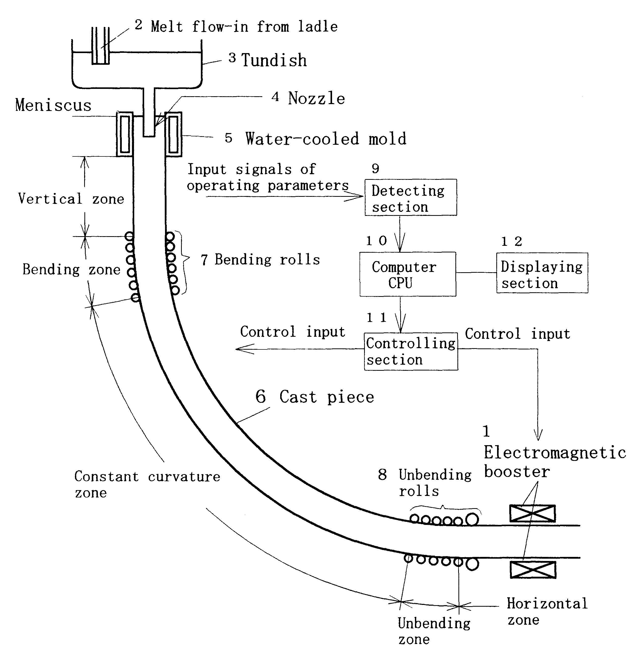
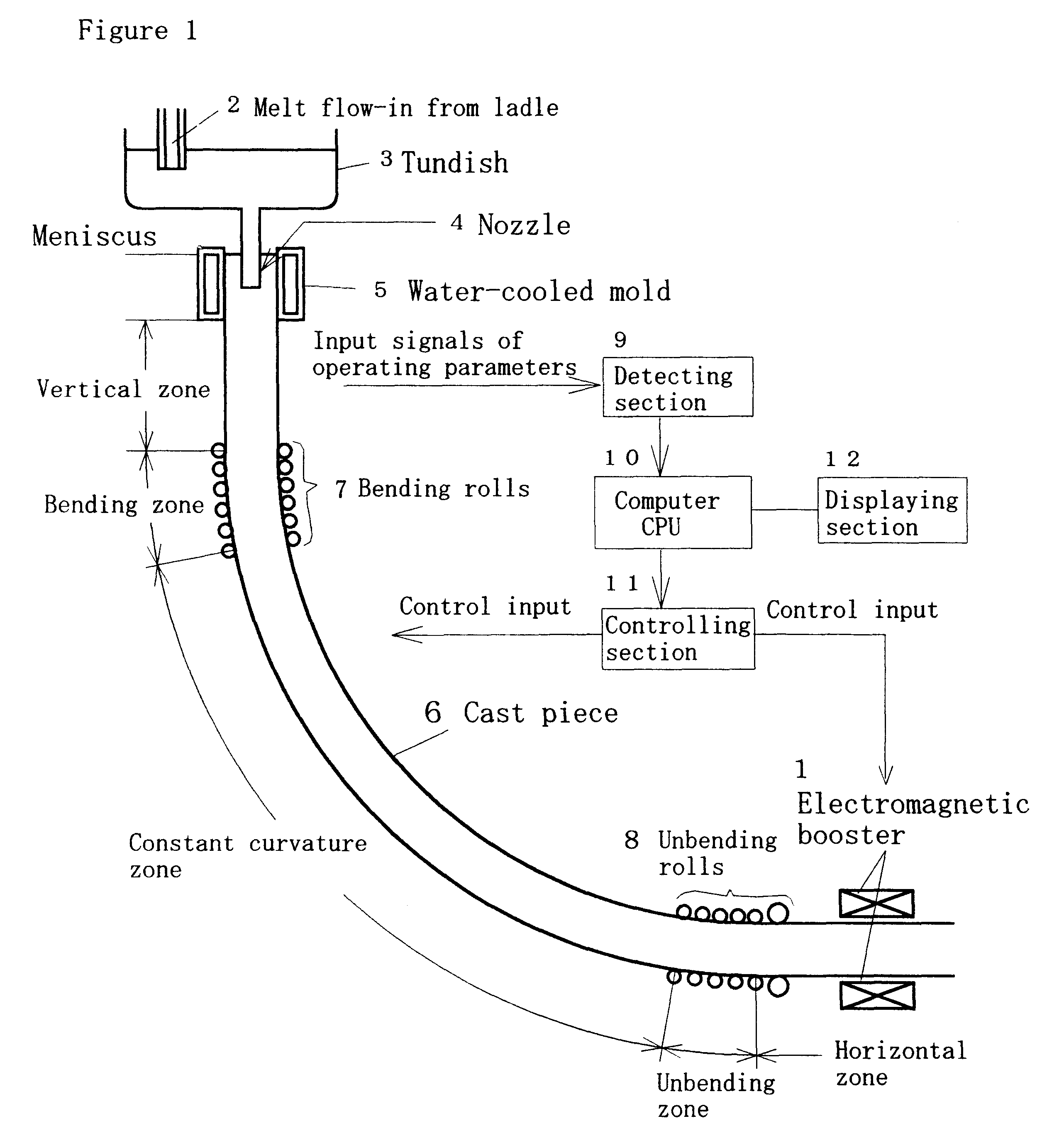
The specific example applied to steel bloom or billet is shown in FIG. 58. With respect to machine profile, vertical-bending type or bending type is most widely used as schematically shown in FIG. 1. FIG. 58 shows the case that the electromagnetic booster is located in the upstream vicinity of the final solidification zone (crater end) at the horizontal zone of cast piece. FIGS. 58(a) is the cross-sectional plan and (b) is AA cross-sectional plan in longitudinal direction. The arrow in the diagram denotes the casting direction. The view from the top, BB cross-section, is shown in FIG. 59.

Symbol 6 in the figure denotes the cast piece and Symbol 102 denotes the electrode located at both sides of the cast piece that contacts with the side surface. The electrode is fixed to the frame 107 (details not shown) with spring 106 and slides against the moving cast piece. The plural number of electrodes is arranged over the Lorentz force zone as shown in FIG. 58(b). Each electrode ...

specific example 2

Case Where the Distance Between Coils is Shortened.

Considering this point, the width of the coil was expanded and the distance between the coils was shortened to obtain a stronger magnetic field compared to Specific example 1. The cross-sectional view is shown in FIG. 63(a). For this, the distance between the coils was shortened by setting up spaces in the upper frame 117 and the lower frame 118 to house the roll units. If the distance between the coils is too short, the coils collide with or approach too close to the cast piece at the position where the coils cross the cast piece. In such a case, horse-saddle type coil may be used to secure a necessary space at both ends of the coil as shown in FIG. 63(b).

This example is basically applied to the case where the driving units of rolls are not required by properly adjusting the balance of the Lorentz force and the drawing resistant force due to soft-reduction (Function II of the above-mentioned). [If the roll drive is inevitably neede...

specific example 3

b

The specific example applied to a wide slab is shown in FIG. 64, where both Lorentz force and small amount of soft-reduction are given. Because the reduction rolls are long and slender and easy to bend due to reduction load and thermal stress, split rolls are used. The reduction force is given by oil-hydraulic cylinder. The reduction is done by upper roll in general and the hydraulic cylinder 127 is attached to each bearing unit. The cylinder stroke may be short as already mentioned. If more margin is necessary, the unit of specific example 2 can be used. As to the roll, one piece of roll may be used whose diameter is squeezed at bearing units or may be divided into split rolls and each of them supported independently at the bearing units. Also, it is desirable to prevent the plastic deformation at the cross-section corners by attaching roundness at both sides of the end rolls. Roll-drive is done by lower rolls in general. Other mechanisms such as electrode are same as those of spe...


PUM

PropertyMeasurementUnit
Fractionaaaaaaaaaa
Fractionaaaaaaaaaa
Fractionaaaaaaaaaa

Abstract

Method and apparatus for continuous casting, especially casting of steel that can easily provide high quality steel that has no central segregation and central porosity. In other words, in the method and apparatus, central defects are to be eliminated first by identifying the solidifying conditions in the full range from the meniscus (the surface position of the upper portion of molten metal) to the crater end (a final solidification position), based on the type (profile) of continuous casting machine, type of steel, cross-sectional shape and size of a cast piece and the operating conditions such as casting speed, casting temperature and cooling conditions, with special attention paid to the pressure drop of liquid phase induced by the liquid flow between dendrites resulting from the solidification contraction in casting direction in the solid-liquid coexisting zone, second by calculating the condition of the formation of the above internal defects and their positions, and finally by applying an electromagnetic body force (Lorentz force) in the casting direction in the vicinity of the region where the internal defects are formed.

Description

This invention is concerned with continuous casting, particularly with a suitable continuous casting method and apparatus to produce highly qualified steels without segregation and porosity.With regard to the continuous castings of carbon steels, low alloy steels, specialty steels and so on, more than twenty years have passed since the present vertical-bending-type continuous casting machines began to operate. And it has been said that these technologies became mature. On the other hand, the demand for the quality is increasing its severity year after year and the pressure to the cost-down also is increasing simultaneously. Aside from the problems such as breakout, etc. that often became a problem in the early period of the operating history, there still remains (1) central segregation and (2) central microporosity as the major problems concerning the quality.The central segregation is the segregation having V characters that takes place with a periodicity in the middle of the thick...

Claims


Application Information

Patent Timeline
IPC IPC(8): B22D11/12B22D11/16
CPCB22D11/122B22D11/16
Inventor EBISU, YOSHIOSEKINE, KAZUYOSHI
Owner EBISU
Why Eureka
Try Eureka