Rotary hammer

Inactive Publication Date: 2001-06-05
BLACK & DECKER INC
View PDF23 Cites 70 Cited by
  • Summary
  • Abstract
  • Description
  • Claims
  • Application Information

AI Technical Summary

Benefits of technology

The tool holder according to the present invention has the advantage that separation of the impact force exerted on the restraining element by the retaining element into its axial and radial components reduces the magnitude of the maximum force experienced by any individual restraining element, with the consequent reduction in the risk of damage to the tool holder.
Preferably the axial restraining block of the tool holder has a surface that is hit by the or each retaining element and which is substantially normal to the axis of the cylinder, at least in the region thereof that is hit by the or each retaining element, so that the axial restraining block is subject substantially solely to the force in the axial direction required to bring the bit to rest, and n

Problems solved by technology

This change has the problem that the magnitude of the reduction of momentum of the bit that is necessary after the last impact by the beat piece in order to bring the bit to rest in the tool holder is increased, with the result that the impact forces exerted on the retaining element by the rear end of the retaining groove of the bit are also increased, which can damage the components of the tool holder.
The problem of damage to the tool holder caused by the impact of the retaining groove of the bit shank on the retaining element depends to a large extent on the distance that is available for the bit to decelerate to rest after having been hit by the beat piece.
However, such a solution is not possible without removing compatibility of the tool holder with existing designs of bi

Method used


Image

  • Rotary hammer
  • Rotary hammer
  • Rotary hammer

Examples


first embodiment

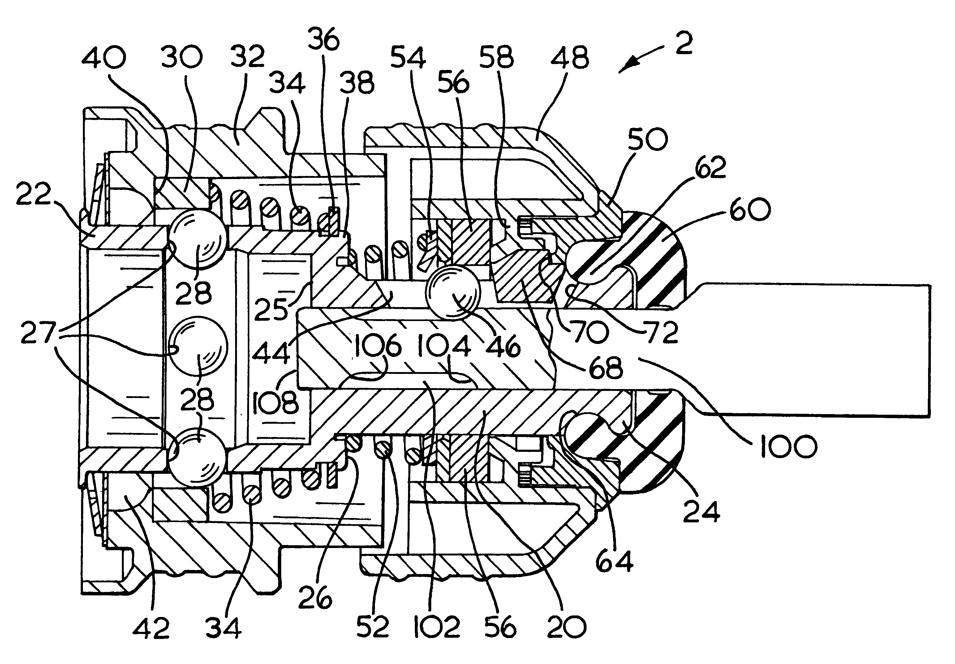
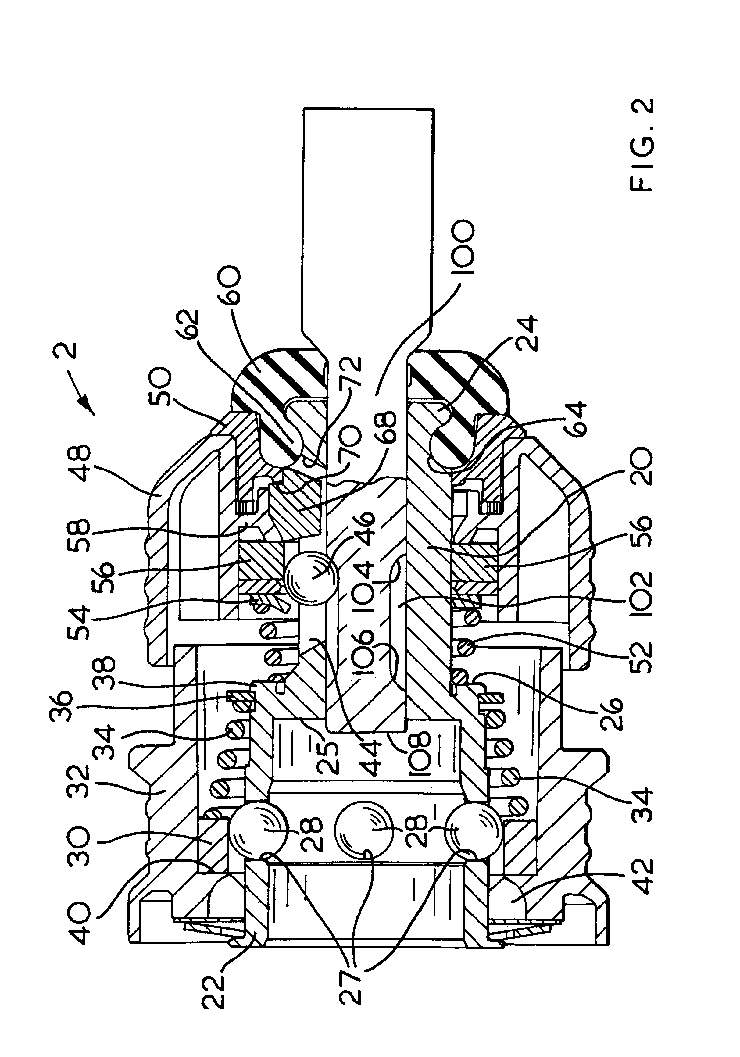
When the rear end of the bit shank 100 is impacted after removal of the bit from the workpiece, the rear end 106 of the retaining groove 102 hits the locking ball 46 and the ball is thrust both radially outwardly and axially forwardly as before. The radial force is countered by the annular restraining element 56, while the axial force causes the axial restraining block 68 to move forward in the aperture 44 by about 2 mm, which movement causes the side of the washer 82 adjacent to the locking ball to move forward by the same amount as shown in FIG. 7. The part of the nose piece 60 located between the metal washer 82 and the support washer 84 is formed as an annulus 90 that is relatively thin (in the radial direction) and therefore more easily deformable than the rest of the nose piece 60. Under the effect of the forward movement, of the washer 82, the thin annulus 90 is deformed axially against the support washer 84 which deformation resists further forward movement of the restrainin...

third embodiment

the tool holder according to the invention is shown in FIG. 8. This form of tool holder is similar to that shown in FIGS. 5 to 7, but the nose piece 60 includes a deformable seal 120 (corresponding to seal 88) formed integrally therewith. Also, a separate deformable annular element 122 is used to dampen the forward movement of the axial restraining block 68 and washer 82 under impact of the restraining element 46.


PUM

PropertyMeasurementUnit
Lengthaaaaaaaaaa
Lengthaaaaaaaaaa
Lengthaaaaaaaaaa

Abstract

A tool holder attachable to a spindle of a hammer and which can receive a bit, the bit having a shank with at least one retaining groove extending along part of the shank, the retaining groove having a defined length, a front end and a rear end that limit axial movement of the bit in the tool holder, which tool holder comprises a hollow cylinder having an axis, an axial bore, a rear end that can be attached to the spindle of the hammer, and a front end that can receive the shank of the bit so that the bit is slidable within the cylinder in an axial direction, at least one retaining element that is located so that it can extend radially into the bore of the cylinder and into the at least one retaining groove of the bit so that the retaining element can be hit by the rear end of the retaining groove during the transition to idling and limit the extent of axial movement of the bit within the cylinder, at least one radial restraining element limiting movement of the retaining element in the radial direction, at least one axial restraining block limiting movement of the retaining element in the axial direction, when hit by the retaining element the axial restraining block movable to a limited extent in the axial direction with respect to the radial restraining element, and a resilient element located forward of the axial restraining block and arranged so as to attenuate the impact transmitted through the axial restraining block from the retaining element.

Description

BACKGROUND OF INVENTIONThis invention relates to rotary hammers and in particular to hammers that incorporate an air cushion hammering mechanism, and to tool holders for use in such hammers.Such hammers will normally include a tool holder that can hold a hammer bit or chisel bit for acting on a workpiece, and an air cushion hammering mechanism which comprises a piston, a beat piece and normally also a ram that are slidably located in a spindle so that reciprocation of the piston in the spindle will cause the beat piece to hit the end of the bit located in the tool holder with a considerable force, thereby to cause the bit to impact the workpiece. Such hammers are well known, and are described, for example in EP-A-0 014 760, EP-A-0 429 475 and EP-A-0 759 341. The tool holders and the bits are arranged so that the bit is able to move to a limited extent in the axial direction under the force of the impact from the beat piece, and so chip at the workpiece. A number of designs have been...

Claims


Application Information

Patent Timeline
IPC IPC(8): B23Q3/00B23Q3/12B25D17/08B25D17/00B23B45/16
CPCB23Q3/12B25D17/088B23B2260/022B25D2211/003Y10T279/17752B25D2217/0065Y10S279/905Y10T279/17068Y10T279/17085B25D2217/0042
Inventor WACHE, ROBERT BERNHARDDROSTE, MANFRED
Owner BLACK & DECKER INC
Why Eureka
Try Eureka