Percutaneous mapping system

a percutaneous mapping and catheter technology, applied in the field of percutaneous mapping systems, can solve the problems of increasing the difficulty of guiding the catheter increasing the difficulty of catheter guiding along the spiral configuration, and increasing the difficulty of myocardial protection and perfusion. achieve the effect of simple and effective percutaneous mapping

Inactive Publication Date: 2001-06-05
MEDICAL SYST
View PDF12 Cites 72 Cited by
  • Summary
  • Abstract
  • Description
  • Claims
  • Application Information

AI Technical Summary

Benefits of technology

It is a further object of this invention to provide such a mapping system which is simple and inexpensive.
The invention results from the realization that a truly simple and effective percutaneous mapping system can be achieved using a wire having a plurality of spaced imaging markers for percutaneous insertion into a body cavity in a spaced configuration with the markers distributed about the inner wall of the cavity, and the further realization that by associating with the markers sensor devices for sensing the electrical potential of the cavity wall in the vicinity of the marker, the presence of ischemic and foreign bodies can be detected.

Problems solved by technology

However, despite advances in treatment techniques, there is a large group of patients who cannot undergo CABG or PTCA due to severe diffuse coronary atherosclerotic disease.
These attempts resulted in temporary increases in myocardial protection and perfusion due to blood flow through the channels but were eventually unsuccessful as the channels quickly closed as a result of the mechanical trauma associated with these procedures.
In U.S. Pat. No. 5,730,741, a spiral member is shown which can be used to map the inside of an organ, but the treatment catheter is constrained to follow the spirals of the spiral member resulting in a loss of power as well as increased difficulty in guiding the catheter along the spiral configuration.
Moreover, this configuration can cause a change in the modality of the transmitted laser beam and serious heating of the optical fiber itself.

Method used


Image

  • Percutaneous mapping system
  • Percutaneous mapping system
  • Percutaneous mapping system

Examples


Embodiment Construction

Other objects, features and advantages will occur to those skilled in the art from the following description of a preferred embodiment and the accompanying drawings, in which:

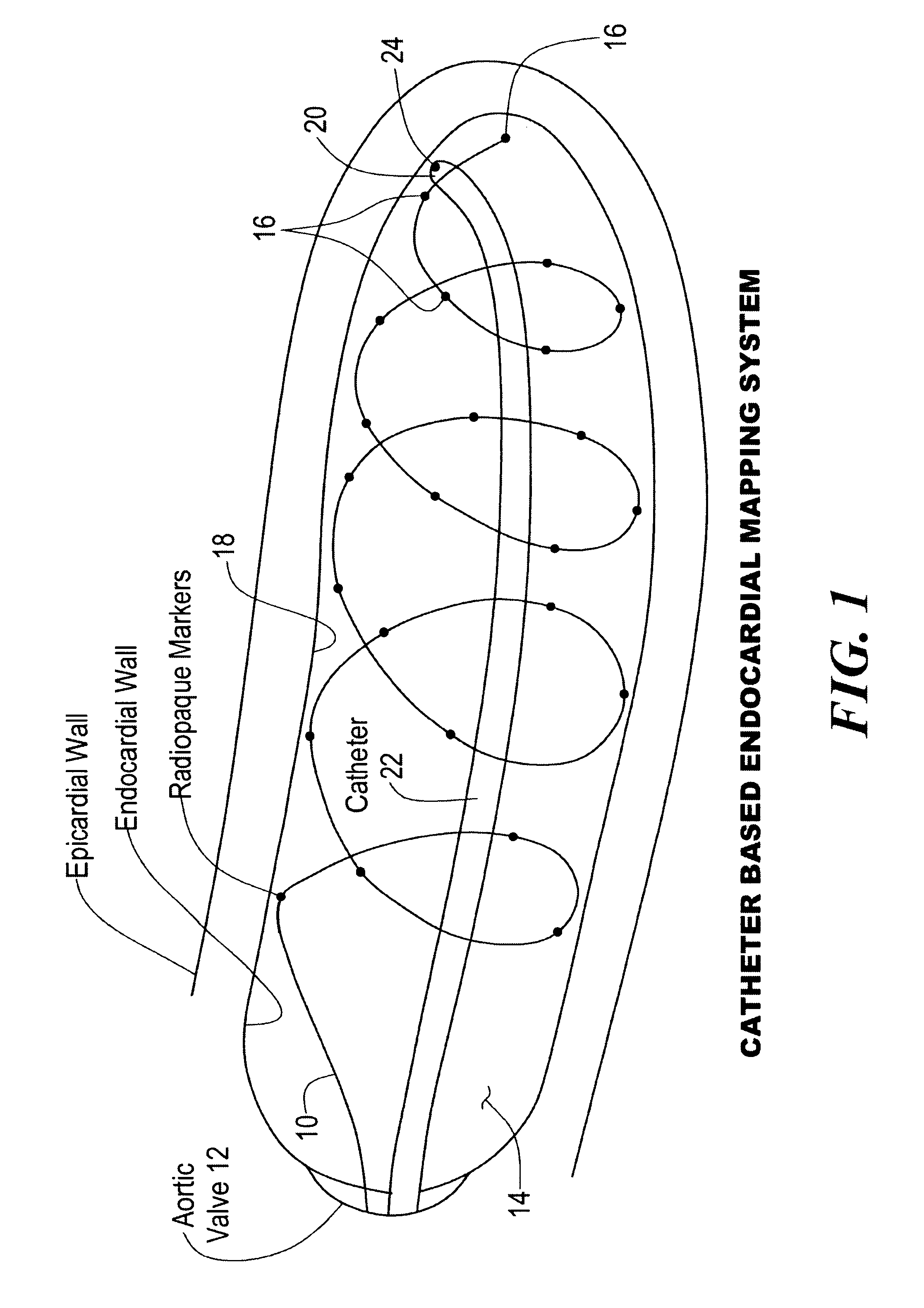
FIG. 1 is an enlarged three-dimensional schematic diagram of a mapping wire spirally disposed in the left ventricle of a heart and accompanied by a treatment catheter;

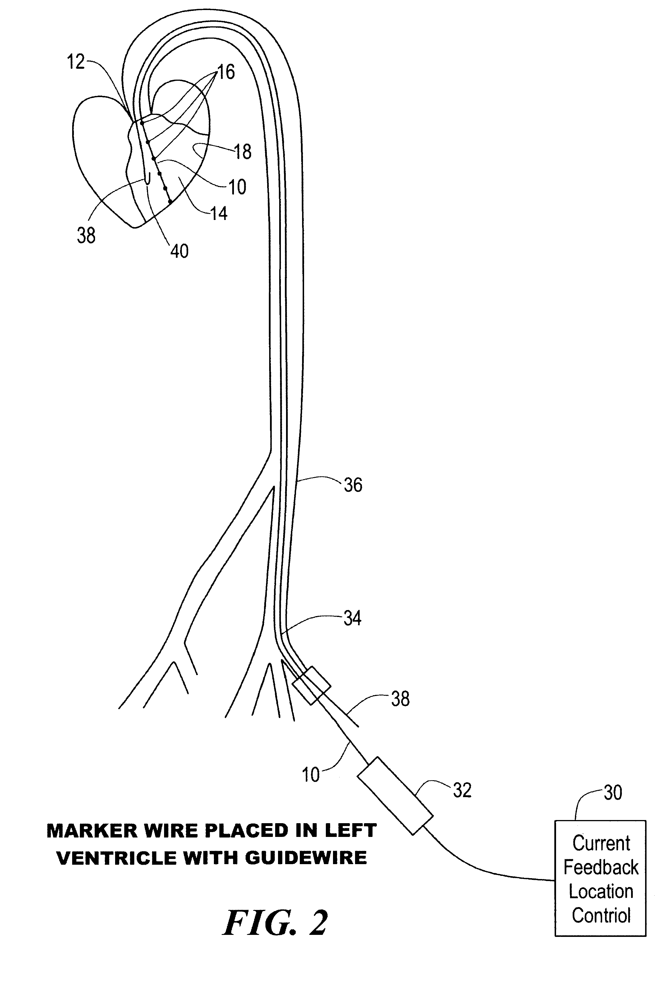
FIG. 2 is a schematic diagram of a mapping wire and a guide wire installed through an introducer sheath into and through an artery into the left ventricle of the heart with the mapping wire in the straight condition;

FIG. 3 is a view similar to FIG. 2 with the mapping wire disposed in a spiral configuration;

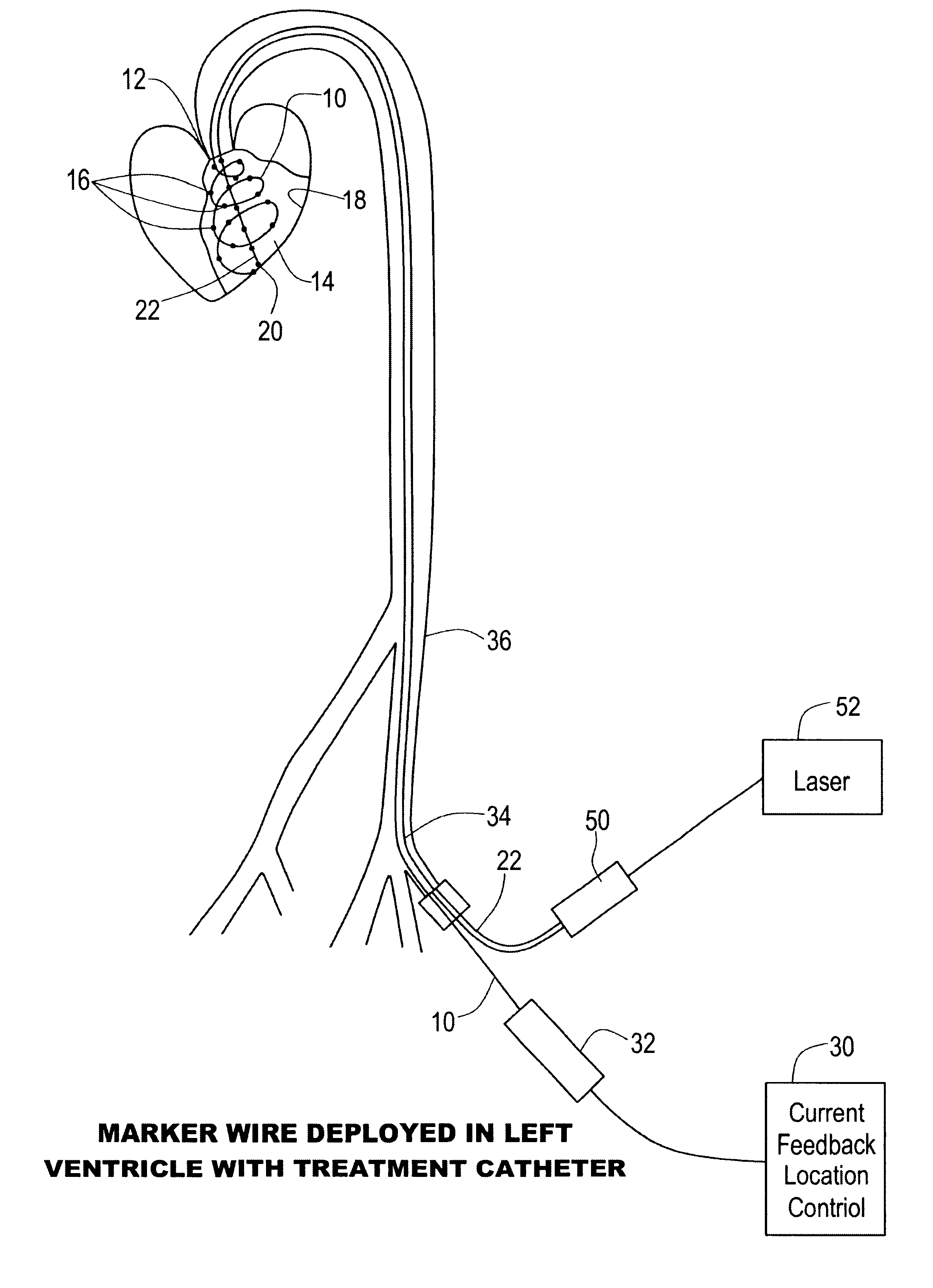
FIG. 4 is a view similar to FIGS. 2 and 3 with a PMR catheter including a laser delivery optic fiber introduced through the artery into the left ventricle of the heart;

FIG. 5A is a side elevational schematic diagram with parts in section of the control device of FIGS. 2, 3 and 4 with the spirally preformed mapping wire tensioned to a straight sh...


PUM


Abstract

A percutaneous mapping system includes a mapping wire, for percutaneous insertion into an internal body cavity, having a plurality of spaced imaging markers; and an insertion device for deploying the mapping wire in a spiral configuration inside the cavity with the markers distributed about the inner wall of the cavity.

Description

This invention relates to an improved percutaneous mapping system and one which can be used to sense the location of ischemic regions in the heart or the presence of an instrument in a body cavity.BACKGROUND OF INVENTIONChronic angina pectoris is a very common disease in the United States. Currently, the most common methods of reperfusing ischemic myocardium are cardiac arterial bypass graft (CABG) and percutaneous transluminal coronary angioplasty (PTCA) operations, with 330,000 and 500,000 such procedures performed every year in the United States. Both techniques restore blood flow to the ischemic myocardium by bypassing or removing the atherosclerotic lesions which obstruct blood flow. However, despite advances in treatment techniques, there is a large group of patients who cannot undergo CABG or PTCA due to severe diffuse coronary atherosclerotic disease.The concept of supplying blood to a myocardium devoid of the natural arterial network is not new. It was discovered many years...

Claims


Application Information

Patent Timeline
Patent Type & Authority Patents(United States)
IPC IPC(8): A61B5/042A61B5/0408A61B6/12
CPCA61B5/0422A61B5/6857A61B6/12A61B2562/0209A61B2562/043A61B5/287
Inventor NEGUS, CHARLES CHRISTOPHERANDREWS, ROBERT R.LINHARES, STEPHEN J.RUDKO, ROBERT I.WOODRUFF, EILEEN A.
Owner MEDICAL SYST
Why Eureka
Try Eureka