Supercharge Your Innovation With Domain-Expert AI Agents!

Thermal imaging medium

a thermal imaging medium and high resolution technology, applied in thermography, instruments, photosensitive materials, etc., can solve the problems of not consistently yielding images of a resolution sufficiently fine, none of the known thermal imaging materials have found wide acceptance, and the time required for irradiating the medium in this manner is relatively short, so as to achieve the effect of improving abrasion resistan

Inactive Publication Date: 2001-06-12
SENSHIN CAPITAL
View PDF31 Cites 19 Cited by
  • Summary
  • Abstract
  • Description
  • Claims
  • Application Information

AI Technical Summary

Benefits of technology

It is a further object of the invention to provide a novel high resolution thermal imaging medium which requires no transfer of the imaging-forming substance from a donor sheet to a receiving sheet.
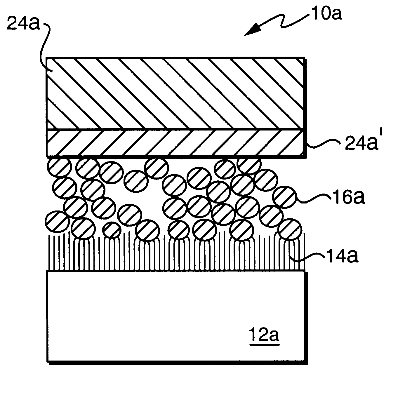
This embodiment offers several distinct advantages: a) The microcrystalline wax release coat 24b' provides an effective protection against abrasion of the image created in the surface 14b; b) the wax release coat 24b' appears to improve the sensitivity of the medium because of its hydrophobic nature which may avoid the necessity of the laser energy "boiling off" water from the coating. Furthermore, the use of a hot melt adhesive in the stripping sheet 24b allows a laminate structure which may provide for an improved automatic peeling by a device integrated into the laser printer.

Problems solved by technology

The time required for irradiating the medium in this manner is relatively short.
None of the known thermal imaging materials appear to have found wide acceptance, possibly because of the relatively complicated mechanism of the image-wise transfer of an image-forming substance from a donor layer to a receiving layer as a result of applied heat patterns.
Other problems may be involved in the coherence of the image-forming substance which may not consistently yield images of a resolution sufficiently fine to be acceptable to consumers.
Still further problems may result from the difficulty of removing microscopical irregularities and air gaps when using two separate donor and receiver webs.
It appears that none of the thermal imaging materials currently available satisfy the demand for high photographic quality or high resolution required by industry.

Method used


Image

  • Thermal imaging medium
  • Thermal imaging medium
  • Thermal imaging medium

Examples


example ii

A carbon black solution containing no polymeric binder or FLUORAD surfactant was prepared from

4.07 g carbon black solution (45% solids) (sold under the tradename Sunsperse Black LHD-6018 by Sun Chemical Co.)

23.93 g water

and coated onto the Mylar web as in Example I, to give a dry coverage of about 0.7 g / m.sup.2. The structure was exposed through the web and developed as in Example I. This example illustrated the the polymeric binder and surfactant present in Example I are not necessary to connect the exposed carbon black firmly to the surface of the web.

example iii

The unexposed carbon black coated web from Example I was coated with a release layer from a solution consisting of:

2.00 g was emulsion (25% solids) (sold under the tradename Michemlube 160 by Michelman Chemicals, Inc.):

7.92 g water;

0.08 g FLUORAD surfactant

with a No. 10 wire-wound rod to give a dry layer coverage of about 0.04 g / m.sup.2. This was overcoated with a stripping layer from a solution consisting of

60.00 g carboxylated ethylenevinylacetate copolymer emulsion (52% solids) (sold under the tradename Airflex 416 by Air Products and Chemicals, Inc.); and

40.00 g polyvinylacetate emulsion (55% solids) (sold under the tradename Daratak 61L by W. R. Grace & Co.)

to give a dry layer coverage of about 20 g / m.sup.2. The structure was exposed through the web by a laser beam with 0.1 J / cm.sup.2 for 1 microsecond. The stripping layer was peeled from the element leaving a negative carbon black image firmly connected to the surface of the web in areas of laser exposure. The stripping layer ...

example iv

The unexposed carbon black coated web of Example III was laminated at about 75.degree. C. to a second Mylar web of 0.1 mm thickness. The laminated structure was exposed through the carbon black coated web of Example III by a laser beam of 0.1 J / cm.sup.2 for 1 microsecond. After exposure the laminate was peeled apart to produce one negative and one positive image. The negative image consisted of exposed carbon black firmly connected to the surface of the web of Example III. The positive image consisted of unexposed carbon black adhered to the surface of the stripping layer, the latter being adhered to the surface of the second Mylar web. The stripping layer was then peeled from the second Mylar web so the latter could be used again for another lamination and peeling.


PUM

PropertyMeasurementUnit
thicknessaaaaaaaaaa
viscosityaaaaaaaaaa
temperaturesaaaaaaaaaa

Abstract

A high resolution thermal imaging medium including a support web having an image forming surface of a material which may be temporarily liquified by heat and upon which is deposited a particulate or porous layer of an image forming substance which is wettable by the material during its liquified state.

Description

1. Field of the InventionThe invention relates generally to a heat mode recording material and, more particularly, to a high resolution thermal imaging medium comprising a heat sensitive layer interacting, at an image-wise application of heat, with an image forming substance for producing images of very high resolution.2. Description of the Prior ArtUnlike the image processing of conventional photographic materials using silver halide emulsions, thermal imaging media require neither a dark room nor any other protection from ambient light. Instead, images may be produced with thermal imaging media by the application of heat patterns corresponding to the image to be produced and, since these materials can provide images by quicker and simpler processes than those applicable to silver halide materials, they are more convenient and economical than conventional photographic imaging materials. Another consideration which contributes to their desirability is that unlike silver halide mater...

Claims


Application Information

Patent Timeline
Patent Type & Authority Patents(United States)
IPC IPC(8): B41M5/26B41M5/36B41M5/46B41M5/40B41M1/18B41M5/24B41M5/382B41M5/385B41M5/392B41M5/395B41M5/41B41M5/42B41M5/44G03F7/34
CPCB41M5/26B41M5/368B41M5/38214B41M5/46B41M5/36Y10T428/24876B41M5/385B41M5/392B41M5/395B41M5/41B41M5/423B41M5/426B41M5/44B41M5/465B41M2205/06Y10S430/146Y10T428/24901Y10T428/24893
Inventor ETZEL, MARK R.
Owner SENSHIN CAPITAL
Features
  • R&D
  • Intellectual Property
  • Life Sciences
  • Materials
  • Tech Scout
  • Unparalleled Data Quality
  • Higher Quality Content
  • 60% Fewer Hallucinations
Learn More