Apparatus for measuring intervals between signal edges

a technology of signal edges and apparatus, which is applied in the direction of instruments, generating/distributing signals, horology, etc., can solve the problems of difficult to accurately predict the gate speed, the speed of the gate is difficult to accurately predict, and the accuracy of the system described above for measuring the time interval between the start and stop signal edges is adversely affected

Inactive Publication Date: 2001-06-12
CREDENCE SYSTEMS
View PDF9 Cites 31 Cited by
  • Summary
  • Abstract
  • Description
  • Claims
  • Application Information

AI Technical Summary

Problems solved by technology

However the clock signal period of a free-running ring oscillator depends on the switching speed of each gate forming the oscillation, and that switching speed is neither stable nor predictable.
Since a logic gate's switching speed depends in part on the nature of the semiconductor material forming it, natural process variations occurring in that semiconductor material make it difficult to accurately predict the speed of the gate.
Thus the accuracy with which the systems described above can measure a time interval between the START and STOP signal edges is adversely affected by unpredictability in the period of the ring oscillator's output signal due to unpredictable process and environmental variations influencing the switching speed of the gates forming the oscillator.
The measurements of the START and STOP delays have an inherent inaccuracy that can be as large as one cycle of the clock signal because timing of the ARMING signal relative to the edge of the timing signal that triggers the counter of each TMU is unpredictable and can vary as much as one full clock cycle.
However since the resulting errors in the start delay measurement and the stop delay measurement performed by the two TMUs are identical, the errors cancel when the decoder subtracts the start delay from the stop delay to determined the interval between the START and STOP signal edges.

Method used


Image

  • Apparatus for measuring intervals between signal edges
  • Apparatus for measuring intervals between signal edges
  • Apparatus for measuring intervals between signal edges

Examples


Embodiment Construction

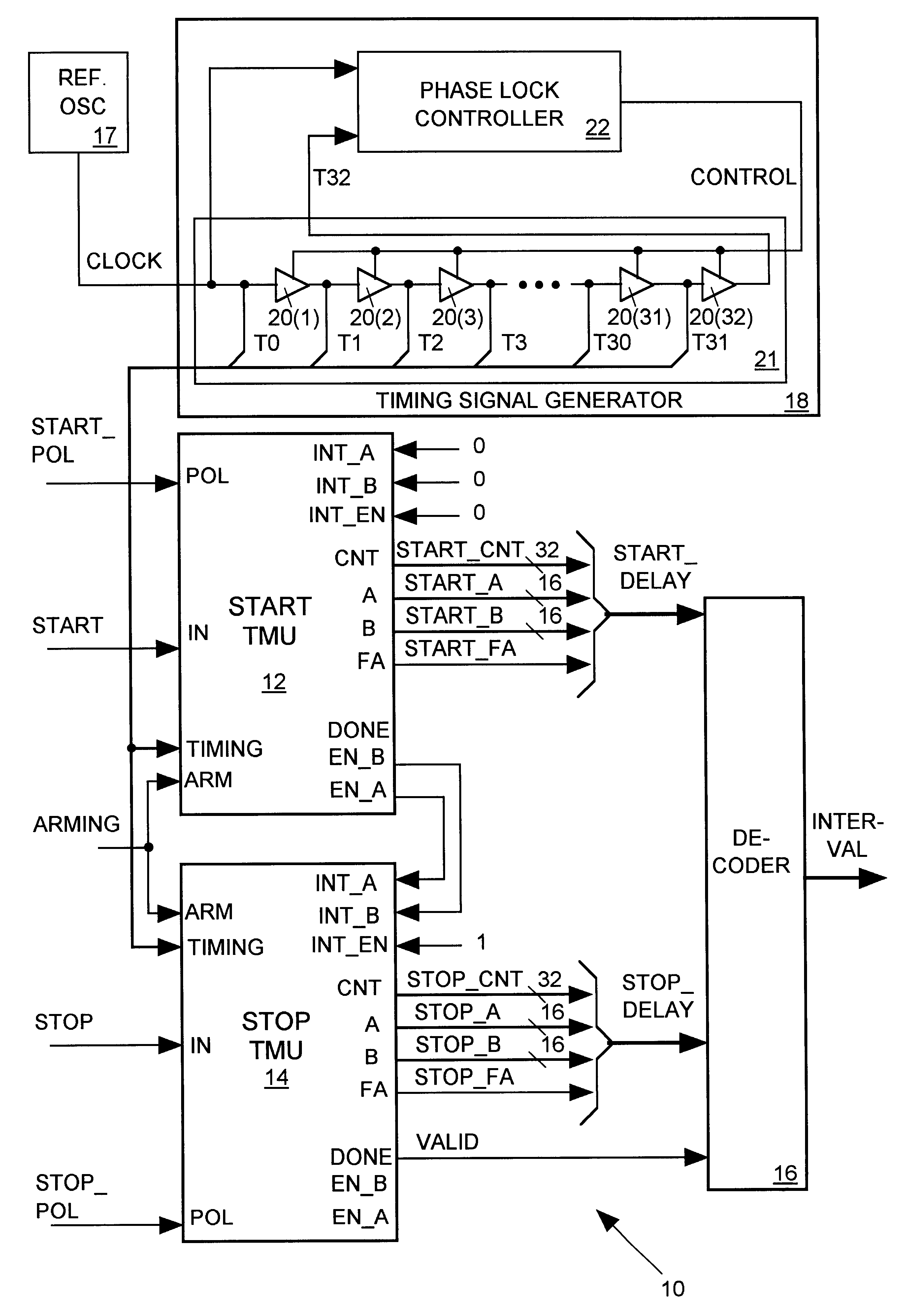
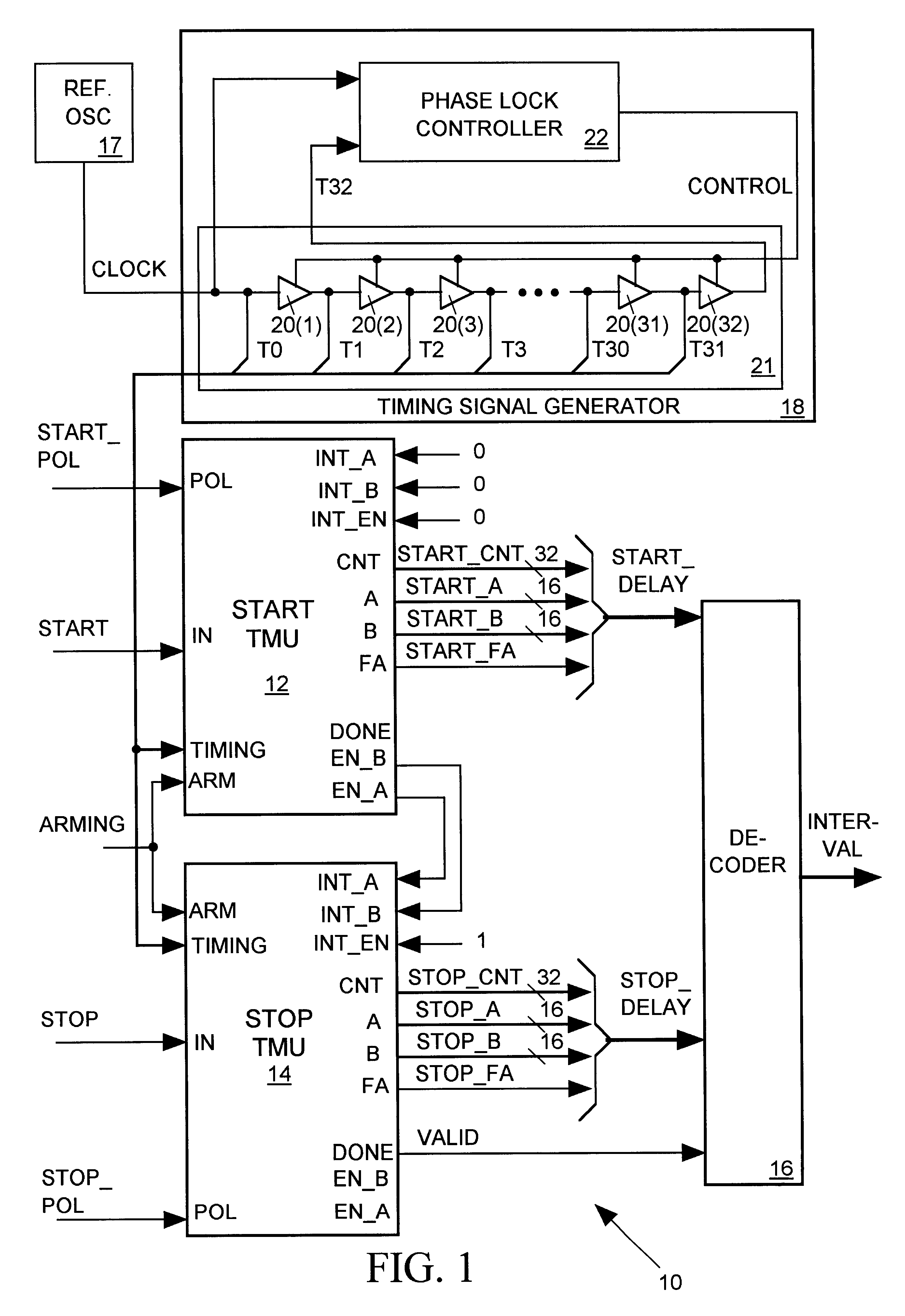
FIG. 1 illustrates a time interval measurement apparatus 10 in accordance with the invention for generating output data (INTERVAL) indicating a time interval between two signal pulse edges (START and STOP). Apparatus 10 includes a start TMU 12 for measuring a delay between a leading edge of a reference signal (ARMING) and the START signal edge and for producing output data (START_DELAY) representing that delay. Similarly a stop TMU 14 measures the delay between the ARMING signal edge and the STOP signal edge and generates output data (STOP_DELAY) representing that delay. As discussed below, start and stop TMUs 12 and 14 both undervalue the delays they measure, but they do so by the same amount. Thus when we subtract the START signal delay reported by the START_DELAY data from the STOP signal delay reported by the STOP_DELAY data, we find that the errors cancel one another and that the result accurately reflects the interval between the START and STOP signal edges. Apparatus 10 inclu...


PUM


Abstract

An apparatus for measuring a time interval between a start signal edge and a stop signal edge provides a stable clock signal as input to a delay line formed by a series of similar logic gates. The output signal of the last gate of the series is phase locked to the clock signal by adjusting a bias signal controlling the switching speed of all gates. The clock signal and the output signal of each gate form a set of phase distributed periodic timing signals applied to a start time measurement unit (TMU) and a similar stop TMU. The start TMU counts edges of one of the timing signals occurring between an edge of an arming signal and the start signal edge and generates output data representing a time delay between the arming signal and the start signal edge. The data represents the start delay as a whole and fractional number of clock signal periods by conveying the counter output and by indicating which of the timing signals had an edge most closely following the start signal edge. The stop TMU similarly produces output data indicating a whole an fractional number of clock cycles occurring between the arming signal and the stop signal edge. The delay represented by the start TMU output data is subtracted from the delay represented by the stop TMU output data to determine the interval between the start and stop signal edges.

Description

1. Field of the InventionThe present invention relates in general to an apparatus for measuring a time interval between two signal edges and in particular to an apparatus employing clock signals of a delay-locked loop delay line as timing references.2. Description of Related ArtOne known system for measuring a time interval between two signal edges employs a crystal oscillator producing a clock signal having a stable, predictable frequency and a counter for counting pulses of the clock signal and producing output data representing its count. A "start" signal edge connects the clock signal to the counter so that it may begin counting clock signal pulses. A "stop" signal edge thereafter disconnects the clock signal from the counter so that it stops counting clock signal pulses. The value represented by the ending count, multiplied by the period of the clock signal, equals the interval between the start and stop signal edges. Unless the start and stop signal pulses happen to be synchro...

Claims


Application Information

Patent Timeline
Patent Type & Authority Patents(United States)
IPC IPC(8): G04F10/04G04F10/06G04F10/00H03L7/081H04L25/38H03L7/08H04L7/04H04L7/033G06F1/12G01R29/02
CPCG04F10/04G04F10/06H03L7/0812H04L25/38H04L7/0337H04L7/044H03L7/081
Inventor KUGLIN, PHILIP THEODORE
Owner CREDENCE SYSTEMS
Why Eureka
Try Eureka