
Method and device in a communication system

a communication system and method technology, applied in the direction of synchronising arrangement, digital transmission, electrical apparatus, etc., can solve the problems of consuming the time in which data could have been transmitted, and the need for complex cross correlation calculations, etc., to achieve simple and inexpensive implementation, simple and fast way, and simple

Inactive Publication Date: 2001-06-26
WI FI ONE
View PDF9 Cites 42 Cited by
  • Summary
  • Abstract
  • Description
  • Claims
  • Application Information

AI Technical Summary

Benefits of technology

An advantage of the present invention is that the symbol rate may be restored in a fast and simple way even before the beginning of a data transmission. During the transmission it may then be sufficient to use a method known in the art for retrieving the sampling rate, because if something locks the sampling rate, the symbol rate is automatically kept constant. Another advantage is that the inventive method is simple and inexpensive to implement.
is that the symbol rate may be restored in a fast and simple way even before the beginning of a data transmission. During the transmission it may then be sufficient to use a method known in the art for retrieving the sampling rate, because if something locks the sampling rate, the symbol rate is automatically kept constant. Another advantage is that the inventive method is simple and inexpensive to implement.
The invention will be described in more detail in the following, by means of preferred embodiments and with reference to the enclosed drawings.
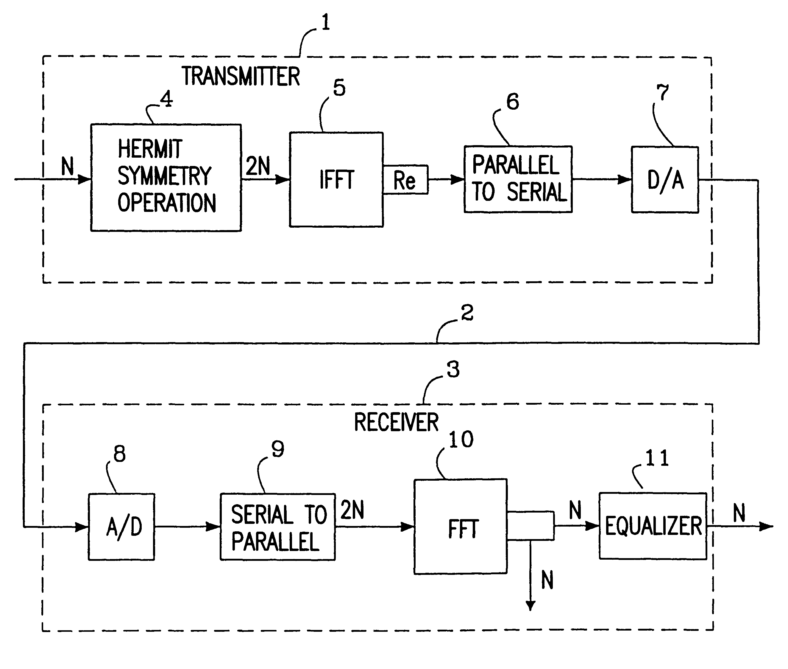
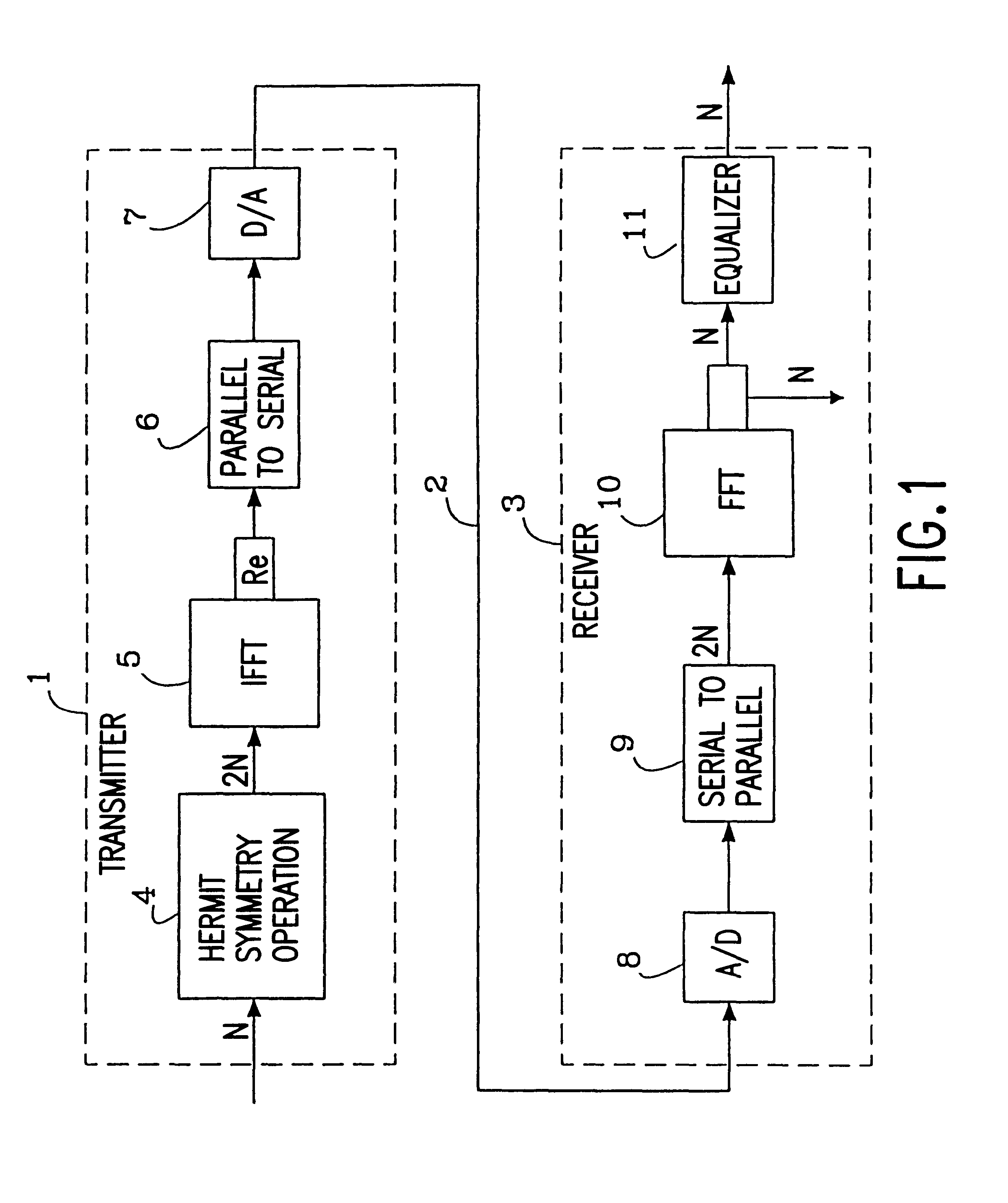
FIG. 1 is a block diagram of a prior art system for multi-carrier modulation.
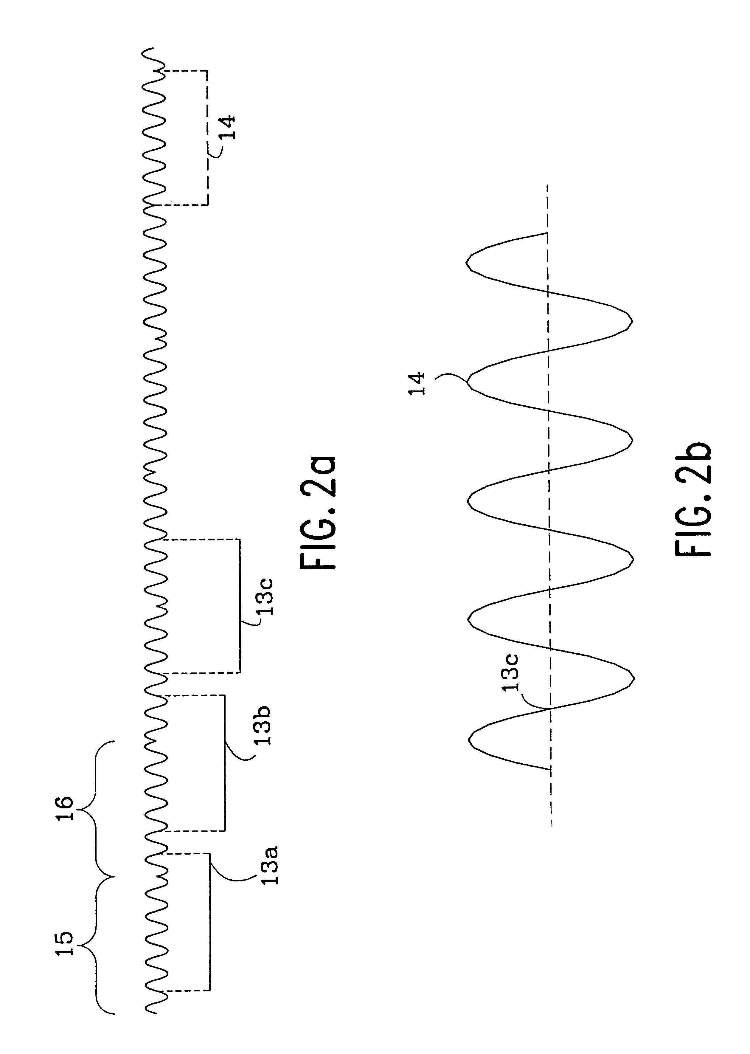
FIG. 2a is a timing diagram of the restoration of the symbol rate according to the invention.
FIG. 2b is a timing diagram of the result of the FFT calculations according to FIG. 2a.

Problems solved by technology

The problem associated with transmitting synchronization symbols at known intervals is that it takes up time in which data could have been transmitted.
Also, a complex procedure of cross correlation calculations is required to detect and analyze the synchronization symbols.

Method used


Image

  • Method and device in a communication system
  • Method and device in a communication system
  • Method and device in a communication system

Examples


Embodiment Construction

Multi-Carrier Modulation

FIG. 1 shows, schematically, how the main parts of a prior art system for multi-carrier modulation may look. In a transmitter 1 modulation of data bits, for example, from a digitally encoded video signal, is performed.

The bits to be transmitted are encoded in the transmitter 1 as N complex numbers before a hermit symmetry operation is carried out in a calculation block 4. 2N complex numbers are obtained having a symmetric real part and an asymmetric imaginary part.

An Inverse Fast Fourier Transform (IFFT) is then performed in an IFFT calculation unit 5, as a modulation. As the imaginary part becomes zero, it may be eliminated, and a real signal remains, which passes a parallel to serial converter 6 and a digital to analogue converter 7.

This gives a sum of orthogonal carriers or tones, the amplitudes and phases of which are determined by the values and phases of the original complex numbers. These carriers are then transmitted on a channel 2 at constant time in...


PUM


Abstract

The present invention concerns a method and a device for the synchronization of a transmitter (1) and at least one receiver (3) in multi-carrier modulated communication systems in which FFT technology is used for the modulation and demodulation of data transmitted between the transmitter (1) and the receiver (3). According to the invention the transmitter (1) transmits synchronization symbols (15, 16) as training symbols (15, 16) at the beginning of a transmission, until a result is obtained that may indicate where a synchronization symbol starts. The result is used for the adjustment of the symbol rate in the receiver (3). Data symbols may then be transmitted after the synchronization symbols (15, 16).

Description

The present invention relates to a method and a device for recovery of sampling rate and symbol rate in multi-carrier modulated communication systems, preferably using copper wires as a transmission medium.STATE OF THE ARTMulti-carrier modulation is a known method for transmitting broadband information over copper wire or radio connections. The information may be, for example, video, Internet or telephony. Very briefly explained, for example, the bits of a digitally encoded video signal that are to be transmitted, are encoded as complex numbers in a transmitter, before an Inverse Fast Fourier Transform (IFFT) is carried out.The IFFT gives, in the modulation, a sum of orthogonal carriers or tones, the amplitudes and phase displacement of which are determined by the values and phases of the complex numbers. These carriers are then transmitted in time slots at constant time intervals and are called symbols. In a receiver a Fast Fourier Transform (FFT) is carried out instead. In this wa...

Claims


Application Information

Patent Timeline
IPC IPC(8): H04L27/26
CPCH04L27/2613H04L27/2662H04L27/2675
Inventor TORE, ANDRE
Owner WI FI ONE
Learn More