
Valve for metered introduction of volatilized fuel

a technology of metered introduction and fuel, which is applied in the direction of valve operating means/releasing devices, machine/engine, service pipe system, etc., can solve the problems of valve soiling in scavenging process, and achieve the effect of easy replacement of protective screen

Inactive Publication Date: 2001-07-03
ROBERT BOSCH GMBH
View PDF7 Cites 21 Cited by
  • Summary
  • Abstract
  • Description
  • Claims
  • Application Information

AI Technical Summary

Benefits of technology

is to refine a valve of the generic type as defined above such that while being highly versatile in terms of its connectors and holders, the value is as invulnerable to dirt as possible and allows high maximum scavenging quantities.
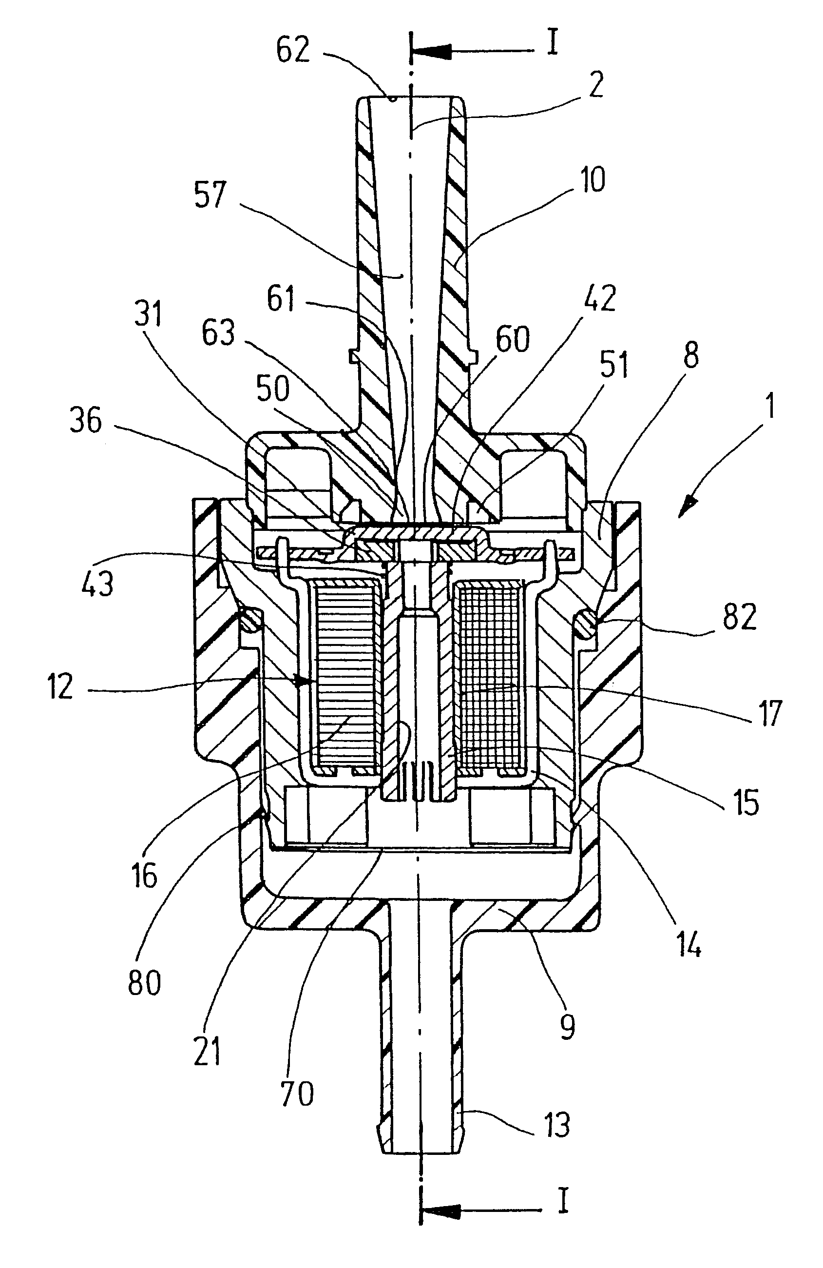
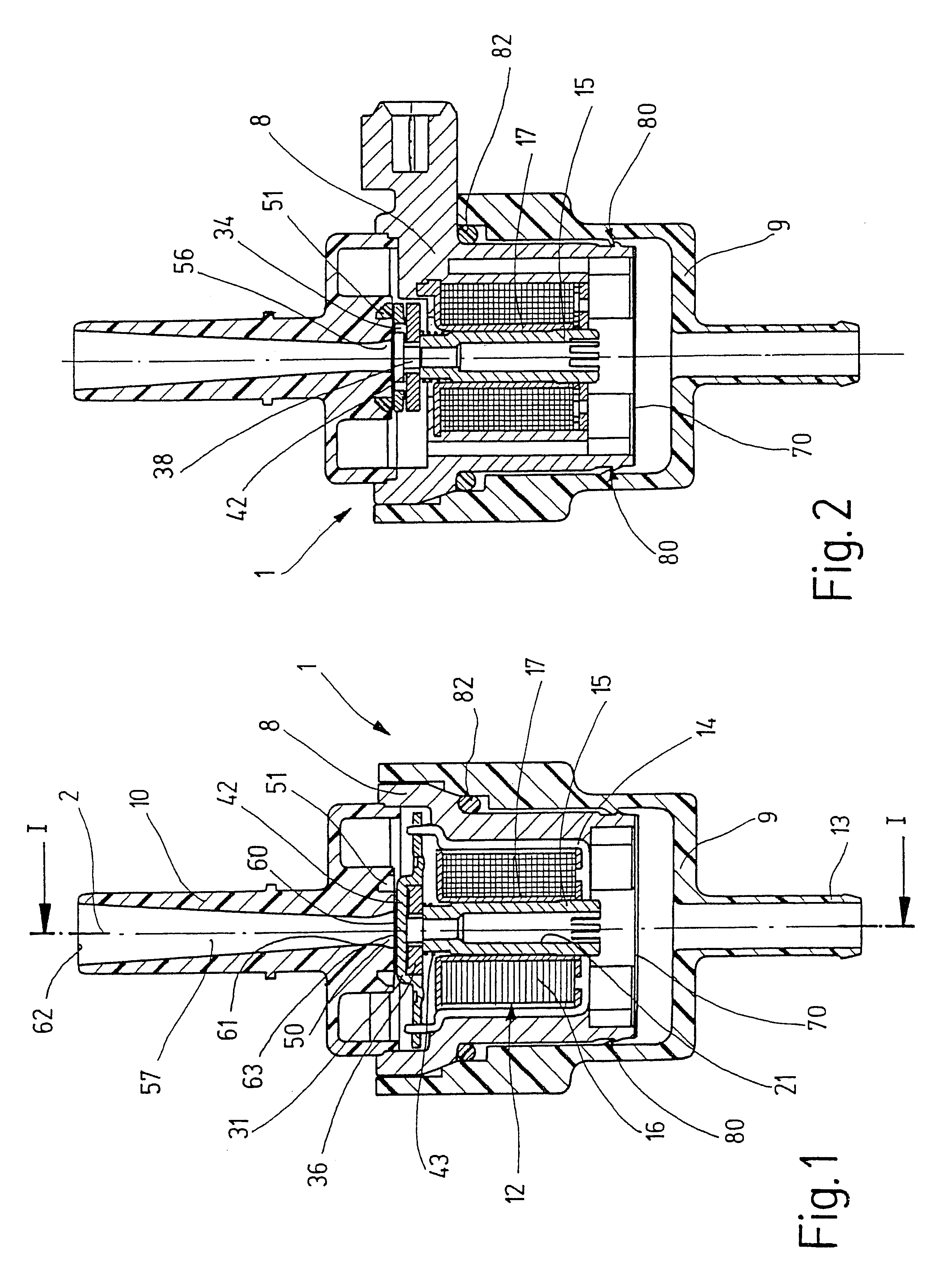
Because of the two-part embodiment: of the valve housing, the modularity of the valve is increased, and producing the value is made considerably simpler. Because of this two-part embodiment, it is possible to postpone producing such type-specific differences as holders, connectors and the like, until the end of valve production, by securing the second part. It is also highly advantageous that the first part is closed on the inflow side by a protective screen. This prevents soiling of the valve, and the protective screen can occupy the entire end face on the inflow side of the first housing part.
In an advantageous embodiment, it is provided that the two housing parts are separably joined together. This exemplary embodiment has the great advantage in particular that if the protective screen becomes stopped up, for instance, it is easily possible to open the housing and replace the protective screen.
Another embodiment provides that the protective screen is separably secured to the first housing part. This embodiment offers the advantage in particular of easy replaceability of the protective screen.

Problems solved by technology

Since such adsorption filters contain activated charcoal particles, soiling of the valve can occur in scavenging processes, as a result of activated charcoal particles that have been torn loose and aspirated.

Method used


Image

  • Valve for metered introduction of volatilized fuel
  • Valve for metered introduction of volatilized fuel
  • Valve for metered introduction of volatilized fuel

Examples


Embodiment Construction

The valve 1 shown in FIG. 1 and FIG. 2 in longitudinal sectional views is used for the metered introduction of volatilized fuel, from a fuel tank of an internal combustion engine (not shown), into an intake tube of an engine, directly into a cylinder of the engine, and the value is part of a fuel vapor trapping system, not shown in further detail, of a mixture-compressing internal combustion engine with externally supplied ignition. The design and function of such fuel vapor trapping systems can be learned for instance from Bosch Technische Unterrichtung Motormanagement Motronic [Bosch Technical Instruction, Motronic Motor Management], 2nd Edition, August 1993, pp. 48 and 49. The design and mode of operation of a valve 1, also known as a regeneration valve or tank venting valve, is known from German Patent Application DE 195 33 742 A1, and in particular from DE 197, 21, 562.9, which are hereby incorporated by reference into the present patent application.

Coaxially to a valve longitu...


PUM


Abstract

A valve for metered introduction of fuel, volatilized from a fuel tank of an internal combustion engine, into the engine, having a valve housing which has an inflow neck for connection to a fuel tank or to an adsorption filter downstream of the tank for the volatilized fuel, and having an outflow neck for connection to the engine, having a valve member accommodated between the inflow neck and the outflow neck in the interior of the valve housing, which valve member is actuatable by an electromagnet that has a magnet core, and which cooperates with a valve seat embodied on a valve seat body, is characterized in that the valve housing includes a first housing part, closed on the inflow side by a protective screen, in / on which the electromagnet, the valve member, the valve seat body and the outflow neck are provided, and a second housing part, on which the inflow neck is disposed and which can be secured to the first housing part.

Description

PRIOR ARTThe invention relates to a valve for the metered introduction of fuel into an internal combustion engine in which the fuel is volatilized from a fuel tank.One such valve is disclosed for instance by German Patent Application DE 195 33 742 A1, and by German Patent Application DE 197 21 562.9, which had not been published by the priority date of the present application.These valves are used to regenerate adsorption filters for fuel vapor trapping systems of the fuel tank of motor vehicles. Since such adsorption filters contain activated charcoal particles, soiling of the valve can occur in scavenging processes, as a result of activated charcoal particles that have been torn loose and aspirated.In known valves, protective screens, protective filters and the like can sometimes be employed only at very great effort, because of the particular design in question.An object of the invention is to refine a valve of the generic type as defined above such that while being highly versat...

Claims


Application Information

Patent Timeline
Patent Type & Authority Patents(United States)
IPC IPC(8): F02M25/08B60K15/077F02M37/00F16K31/06
CPCF02M25/0836Y10T137/8122F02M25/08
Inventor KRIMMER, ERWINSCHULZ, WOLFGANGMIEHLE, TILMANZIMMERMANN, MANFREDESPERILLA, MARIA
Owner ROBERT BOSCH GMBH
Learn More