Copy system and copy controller

a copy controller and copy system technology, applied in the direction of electrographic process, digital output to print units, instruments, etc., can solve the problems of difficult beginners using the conventional color copy system (untrained persons), and achieve the effect of reducing the overall amount of processing reducing the capacity of the memory provided in the copy controller, and simple operation

a copy controller and copy system technology, applied in the direction of electrographic process, digital output to print units, instruments, etc., can solve the problems of difficult beginners using the conventional color copy system (untrained persons), and achieve the effect of reducing the overall amount of processing reducing the capacity of the memory provided in the copy controller, and simple operation

US6256105B1Inactive Publication Date: 2001-07-03SILVER SEIKO LTD

Image

  • Copy system and copy controller
  • Copy system and copy controller
  • Copy system and copy controller

Examples


Embodiment Construction

An embodiment of the present invention will be described with reference to the accompanying drawings.

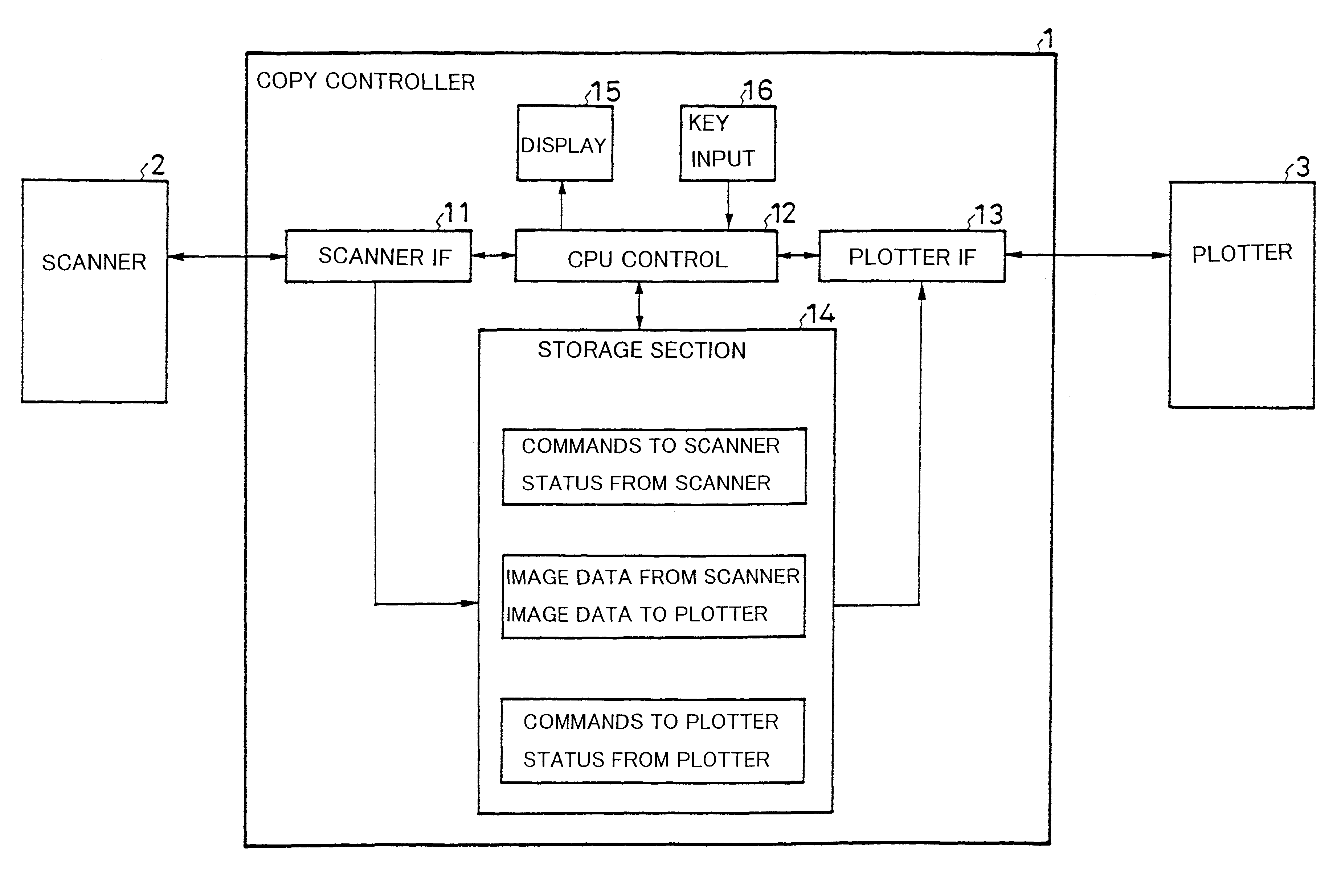
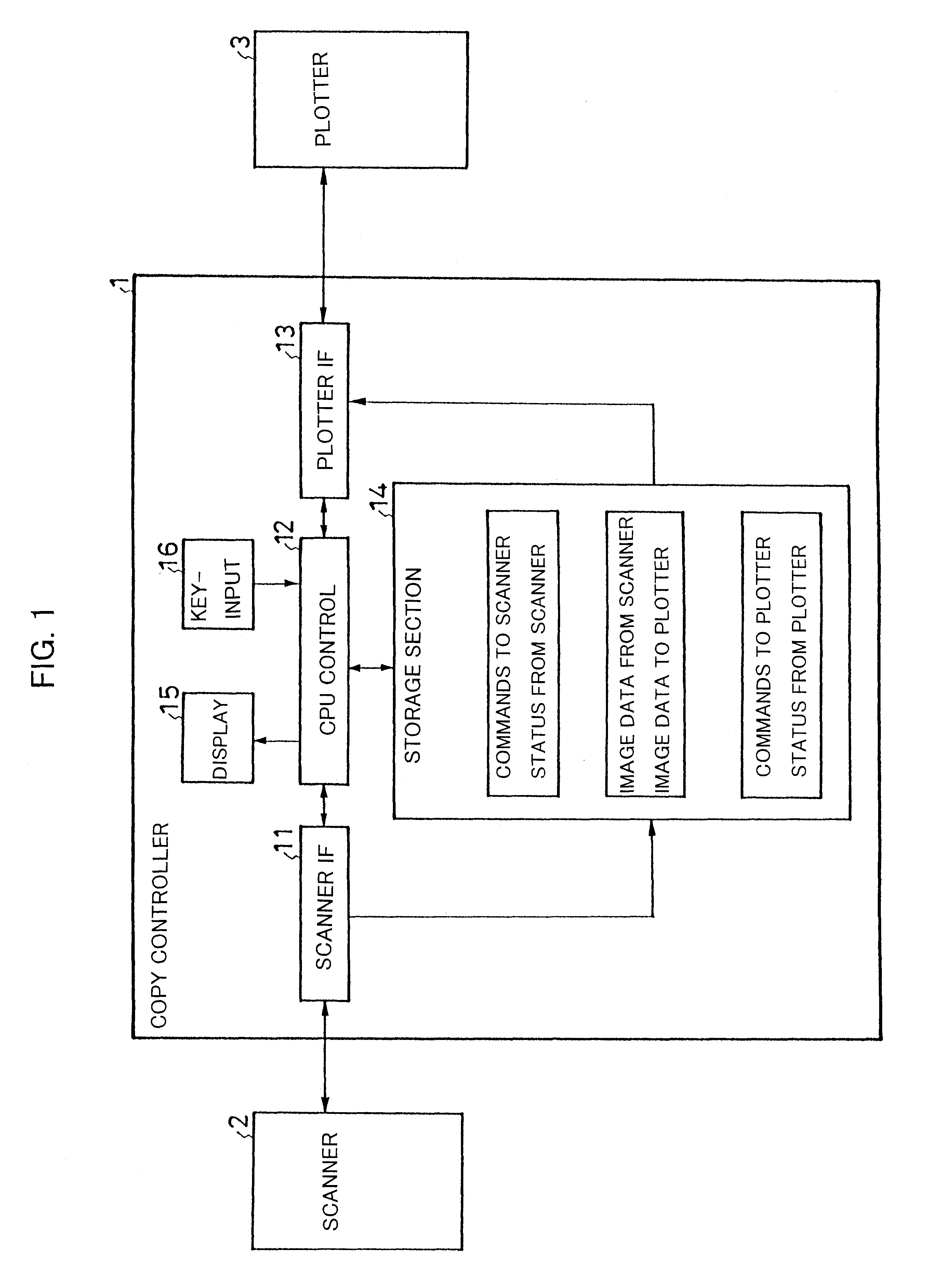
As shown in FIG. 1, a copy system according to the present embodiment is mainly composed of a copy controller 1, a scanner 2, and a plotter (or printer) 3.

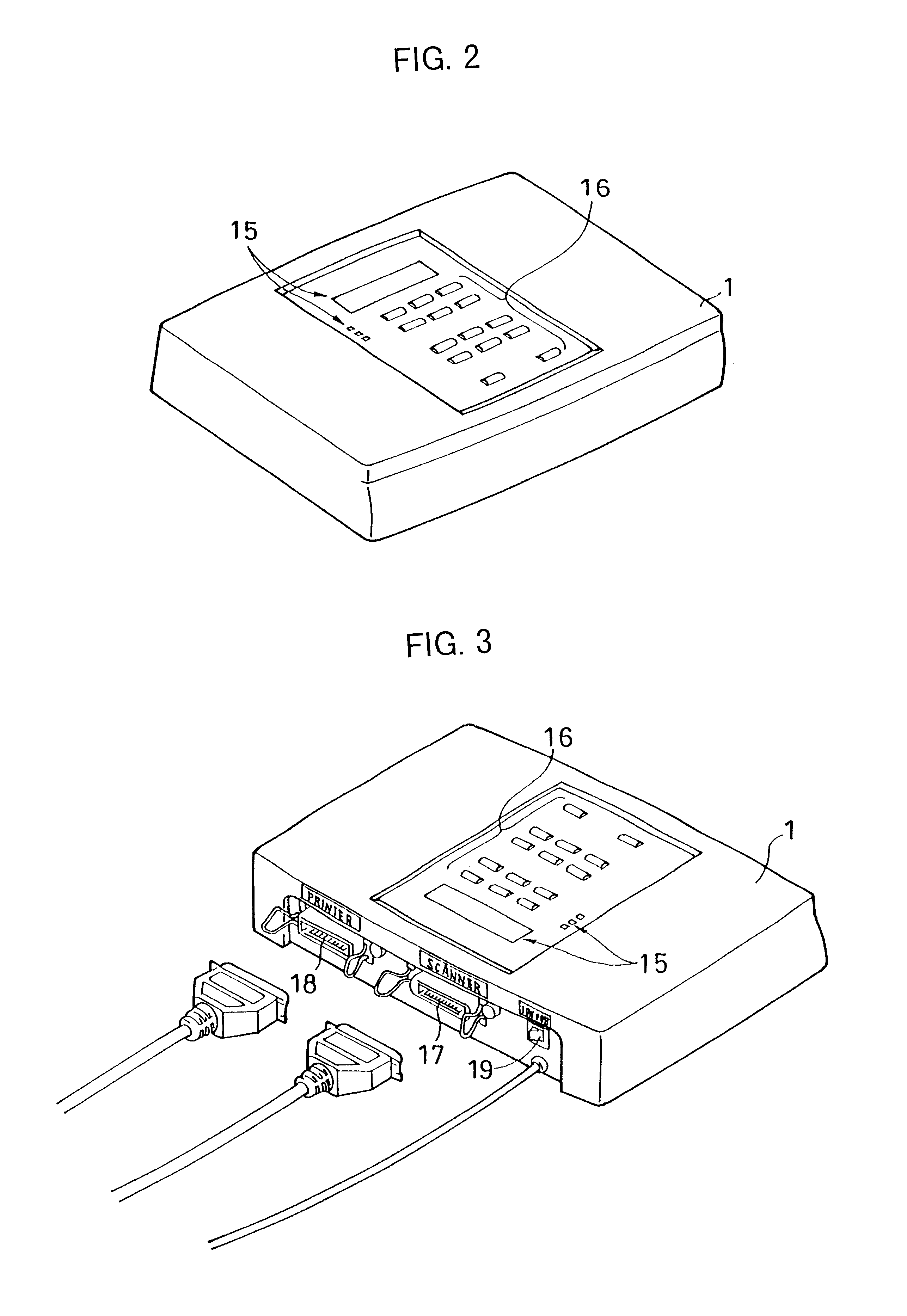
The copy controller 1 includes a scanner interface section (hereinafter referred to as the "scanner IF section") 11, a central processing unit control section (hereinafter referred to as the "CPU control section") 12, a plotter interface section (hereinafter referred to as the "plotter IF section") 13, a storage section 14, a display section 15, and a key-input section 16.

In the present embodiment, the scanner 2 is a color scanner of a line-by-line (one path) type adapted to read A4 documents to be copied. The scanner 2 has a dedicated bidirectional parallel interface or a SCSI (Small Computer Systems Interface). The resolution and other specifications of the scanner 2 can be set through use of commands input from the outside throu...


PUM


Abstract

A copy system includes a copy controller which is connected to a scanner and a plotter via interface sections. Based on key input from a key-input section, the CPU control section of the copy controller inputs image data from the scanner one line or one block at a time and stores the image data into a storage section. After the image data is subjected to image processing, the CPU control section immediately outputs the image data to the plotter one line or one block at a time.

Description

1. Field of the InventionThe present invention relates to a copy system and a copy controller, and more particularly to a copy system composed of a scanner, a plotter, and a copy controller, as well as to the copy controller itself.2. Description of the Related ArtA conventional color copy system is generally composed of a computer into which an image processing program has been installed, and a color scanner and a color plotter connected to the computer via cables. Since such a conventional system has been designed to provide high performance, a user is required to have expert level technical knowledge on color management, and to memorize how to set and operate the image processing program through use of a thick manual. Therefore, using the conventional color copy system is difficult for beginners (untrained persons).Moreover, in the conventional color copy system, after complete image data of an original document obtained through use of a scanner are first stored into a magnetic d...

Claims


Application Information

Patent Timeline
03 Jul 2001
Publication
US6256105B1
IPC
H04N1/00; H04N1/32; G06F3/13; G06T1/60; H04N1/04
CPC
H04N1/00127; H04N1/00238; H04N1/00241; H04N1/00384; H04N1/32; H04N1/00278; H04N2201/3294; H04N2201/0034
Inventors
NOBUAKI, YOKOYAMA; SEIICHI, NISHINO