
Adjustment method of dot printing positions and a printing apparatus

a technology of printing apparatus and adjustment method, which is applied in the direction of printing mechanism, error detection/correction, instruments, etc., can solve the problems of uneven density of images, increase in printing apparatus cost, and difficulty in printing apparatus to achieve this effect, and achieve excellent operation performance and low cost

Inactive Publication Date: 2001-07-10
CANON KK
View PDF26 Cites 77 Cited by
  • Summary
  • Abstract
  • Description
  • Claims
  • Application Information

AI Technical Summary

Benefits of technology

FIG. 7 is a schematic view of a heater board HB being used in this embodiment. Temperature regulating heaters or sub heaters 80d for controlling temperature of the head, an ejection section row 80g in which ink ejecting heaters or main heaters 80c are arranged and a driving device 80h are formed on the same board under a positional relationship as shown in this drawing. The heater board is usually a chip of Si wafer and in addition, by an identical semiconductor deposition process each heater and the driving section required are formed thereon. By disposing these elements on the same board as mentioned above, it permits to detect and control the temperature of the head with high efficiency, and further, to make the head compact and simplify a fabricating process thereof.
Further, is allows to perform simply and rapidly an appropriate dot alignment in accordance with respective modes provided by a printing apparatus, such as a rapid printing or a high resolution printing.

Problems solved by technology

However, to form such a feedback controlled system causes an increase in the cost of the printing apparatus.
As a result, it is difficult to realize this in a printing apparatus which is relatively cheap.
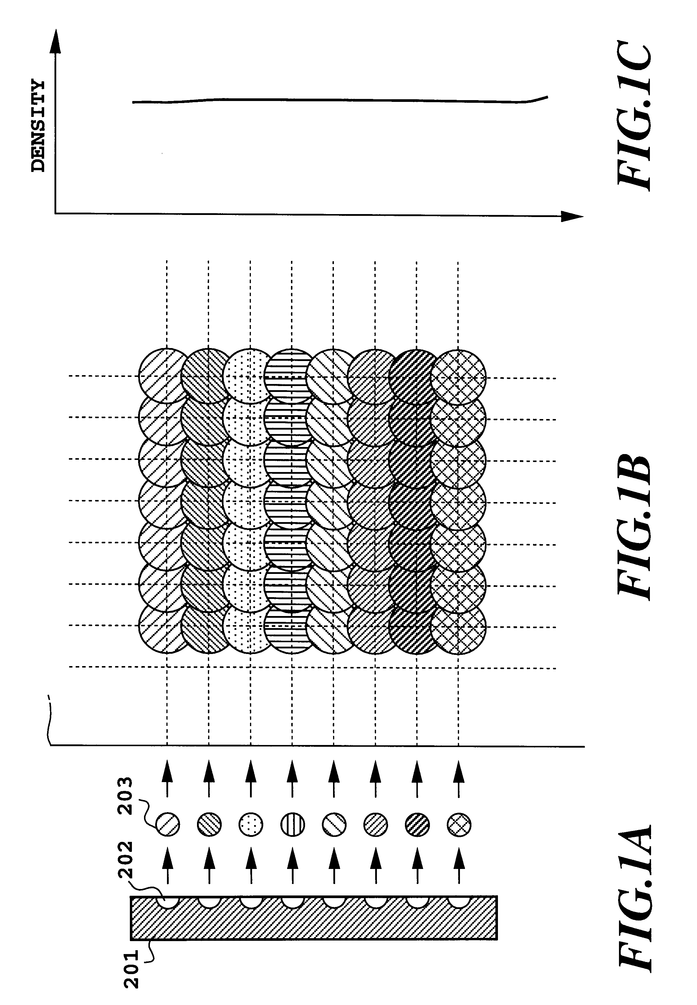
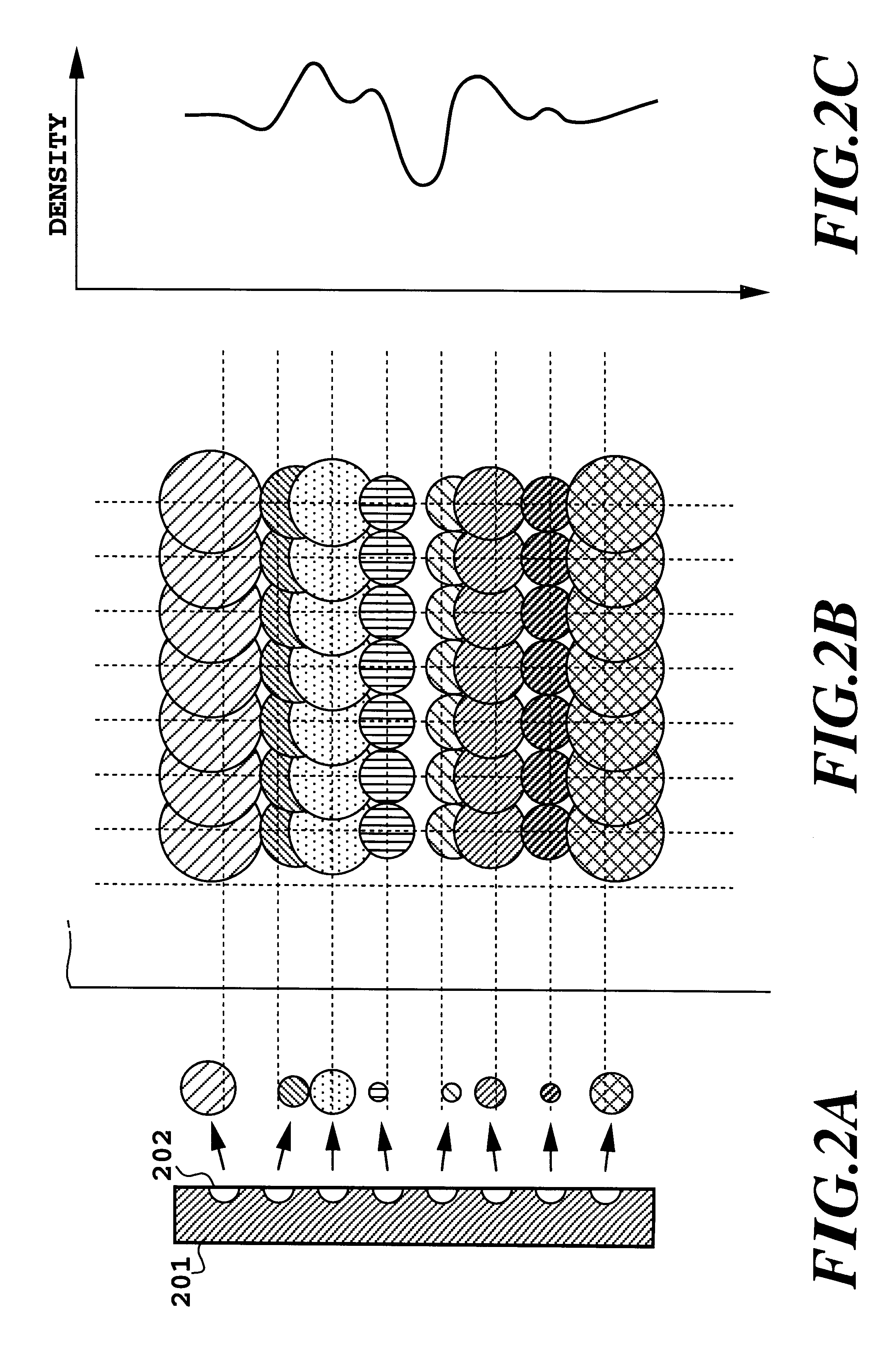
For example, in the case of the ink-jet print head, slight differences, which is generated in a print head manufacturing step, such as variations of a form of ink ejection openings and the elements for generating energy for ejecting ink such as an electro-thermal converting elements (ejection heaters), influence a direction and an amount of ejected ink, and result in an unevenness in density of the image which is formed finally thereby reducing the image quality.
(Problems upon performing image-formation by bi-directional printing) Due to bi-directional printing, the following problems has been caused.
In many cases, the ruled line is formed by a black color, however, though the offset in the ruled line has been understood as the problem where a monochrome image is formed generally, a similar phenomenon can be caused in the color image also.
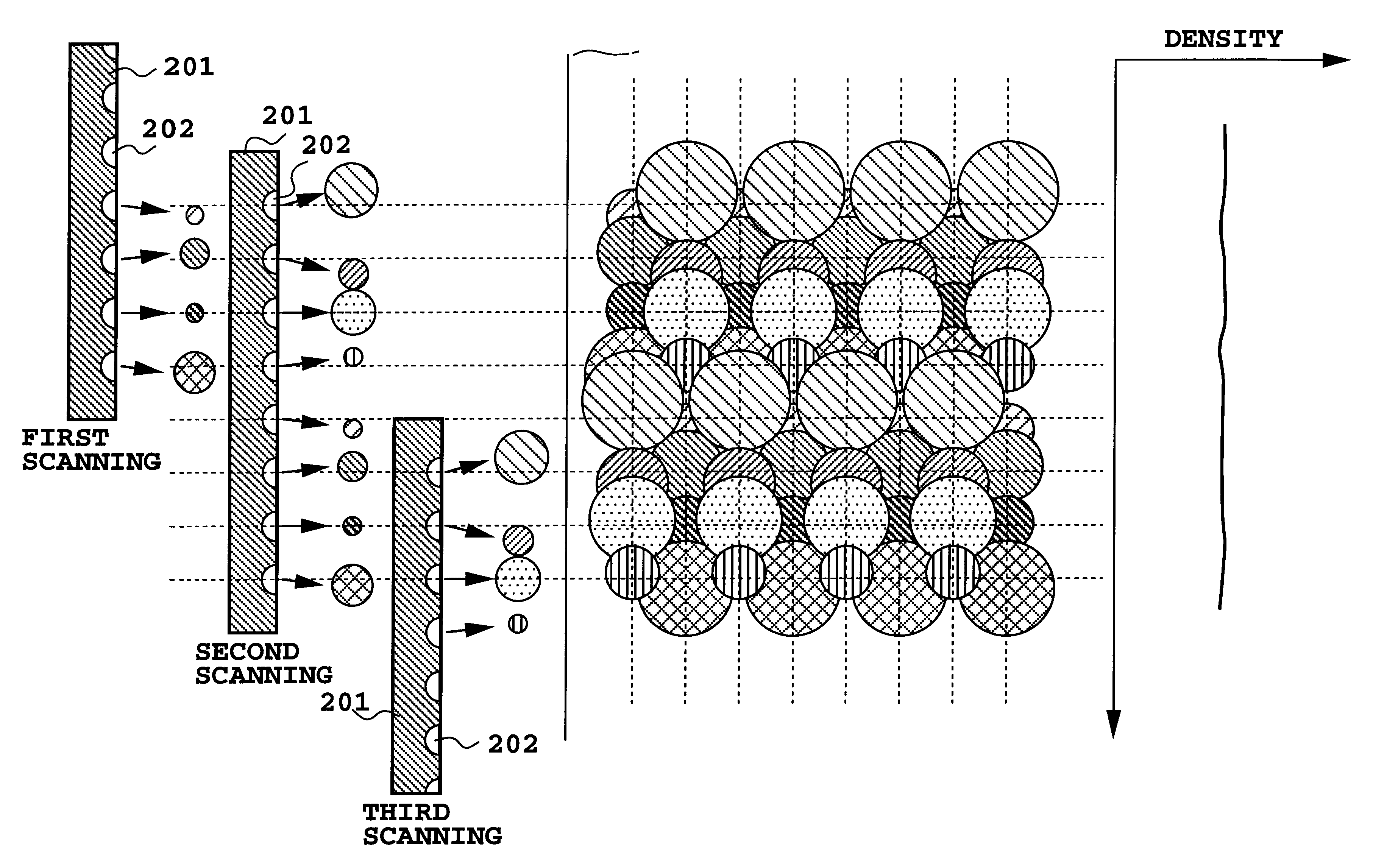
When multi scanning printing is used along with bi-directional printing in order to improve in high image quality, even though in bi-directional printing the depositing positions are not registered, as an effect of the multi scanning printing the offset in the pixel level is not easy to be seen, but from a macroscopic viewpoint the entire image can be seen unequally and is recognized as an unpleasant figure by the user.
(Problems in the case of performing the image formation using a plurality of the print heads)
Moreover, though this deviation in color matching does not become easy to be seen in the case of an ordinary paper, it becomes easy to be seen, when a favorable printing medium in color development such as a coat paper is used.
However, the complicatedness that the user should observe the results which the depositing registration conditions are varied by the eyes to select the optimized the depositing registration condition to perform entering operations is accompanied, and moreover, since fundamentally, a judgment for obtaining the optimum printing position by observing through eyes is enforced on the user, the establishment which is not optimized can be set.
Therefore, it is especially unfavorable to the user who is not accustomed to operation.
Moreover, the user spends time and effort at least two times since the user should print the image to perform the depositing registration and in addition, to perform conditional establishment after observing to perform judgments required, whereby upon realizing the apparatus or a system excellent in operability, it is not only desirable but also is disadvantageous from the viewpoint of time-consumption.

Method used


Image

  • Adjustment method of dot printing positions and a printing apparatus
  • Adjustment method of dot printing positions and a printing apparatus
  • Adjustment method of dot printing positions and a printing apparatus

Examples


first embodiment

3. First Embodiment of Dot Alignment (Printing Registration) Processing

FIG. 13 shows procedures of an automatic dot alignment processing in this embodiment. Here, means for starting this procedures may be a start switch disposed on a body of the printing apparatus, a command from an application on the host computer, and moreover, a timer starting at the moment of the apparatus turn-on, or other convenient means. Further, these may be combined.

Moreover, FIG. 14 is an illustrative drawing of an example of a print pattern formed or used by the execution of the procedures.

When the procedures of FIG. 13 is started (step S1000), a printing medium 8 is fed to the printing position to form print patterns, and sample patches are formed first (step S1002).

Here, an adjustment between a forward printing and a reverse printing (corresponding respectively to the first printing and the second printing) in the bi-directional printing is supposed to be performed. First, in the forward direction, a p...

second embodiment

4. Second embodiment of dot alignment processing

In the aforementioned first embodiment, the sample patches SP1 to SP8 for determining the relationship between the relative offset between the forward printing and the reverse printing and the output of the density sensor (optical sensor 30) are printed by forming patch elements respectively in the forward and reverse scans. On the other hand, in this embodiment, the following sample patches are printed in any one of forward and reverse scans.

In other words, in this example,

SP11: a patch in which a dot-forming area for 8 dots and a blank area for 0 dot appear alternately and repeatedly within a predetermined width from the leftmost pixel column of the patch absolute position reference to the right,

SP12: a patch in which a dot-forming area for 7 dots and a blank area for 1 dot appear alternately and repeatedly within the predetermined width from the leftmost pixel column of the patch absolute position reference to the right,

SP13: a patc...


PUM


Abstract

A plurality of patterns respectively having different area factor of dot formation area are formed by forward and reverse scanning printing of a print head, and then optical characteristics of the plurality of formed patterns are measured. A function representing the relationship between the printing position offset between the forward and reverse printings is determined from the optical characteristics. Then, respective pattern having a predetermined area factor of dot formation area is formed by means of forward and reverse scanning where the speed is differentiated according to the mode of a printing apparatus, and then the optical characteristics of this pattern is measured. By applying this measured optical characteristics to the function, an adjustment value of the dot formation position conditions between the forward and reverse scans is obtained for each mode. This makes it easy to perform printing registration in a printing apparatus in the case of printing by a forward and reverse scan of a printing head or in the case of printing by means of a plurality of printing heads. In this case, operations by a user etc. are also unnecessary and are easily performed.

Description

1. Field of the InventionThe invention relates to a method for adjusting dot forming or depositing positions in dot matrix recording and a printing apparatus using the method. More particularly, the invention relates to a method for adjusting dot forming positions, which are applicable to printing registration in the case of bi-directionally printing by a forward and reverse scan of a print head or to printing registration in the case of printing by means of a plurality of print heads, and printing apparatus using the method.2. Description of the Related ArtIn recent years, office automation instruments such as the personal computer and the word processor, which is relatively cheap, are widely used, and an improvement in high-speed technique and an improvement in high image quality technique of various recording apparatuses for printing-out the information which are entered by the instruments are being developed rapidly. In recording apparatuses, a serial printer using a dot matrix ...

Claims


Application Information

Patent Timeline
IPC IPC(8): B41J19/14B41J19/00B41J2/21B41J2/01B41J2/485B41J2/51B41J19/18B41J29/46
CPCB41J19/145B41J2/2135
Inventor IWASAKI, OSAMUOTSUKA, NAOJITAKAHASHI, KIICHIRONISHIKORI, HITOSHITESHIGAWARA, MINORUCHIKUMA, TOSHIYUKI
Owner CANON KK
Learn More